PMJ5918TSR Ericsson Power Modules, PMJ5918TSR Datasheet - Page 5
PMJ5918TSR
Manufacturer Part Number
PMJ5918TSR
Description
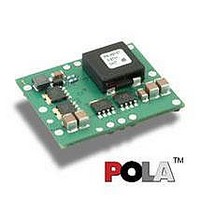
DC/DC Converters & Regulators 0.8-3.6V 30A Non-Iso Input 5V 108W
Manufacturer
Ericsson Power Modules
Series
PMJr
Datasheet
1.PMJ5918TSR.pdf
(32 pages)
Specifications of PMJ5918TSR
Product
Non-Isolated / POL
Output Power
108 W
Input Voltage Range
4.5 V to 5.5 V
Number Of Outputs
1
Output Voltage (channel 1)
0.8 V to 3.6 V
Output Current (channel 1)
30 A
Output Type
POLA Non-Isolated Regulator
Lead Free Status / Rohs Status
Lead free / RoHS Compliant
Available stocks
Company
Part Number
Manufacturer
Quantity
Price
Company:

Part Number:
PMJ5918TSR
Manufacturer:
ERICSSON
Quantity:
12 000


1.0 V/30 A Electrical Specification
T
Typical values given at: T
Additional C
Connect the sense pin, where available, to the output pin.
Characteristics
V
V
V
C
P
η
P
P
P
I
f
V
V
V
t
t
t
t
t
I
I
V
Note 1: Output filter according to Ripple & Noise section
Prepared (also subject responsible if other)
SEC/D KEVIN YAN
Approved
SEC/D Wei Zhang A
PMJ 5000 series
POL regulator, Input 4.5-5.5 V, Output 30 A/108 W
S
s
tr
r
s
f
Inh
O
lim
ref
I
Ioff
Ion
O
d
li
RC
Oi
O
tr
Oac
I
= -40 to +85ºC, V
Input voltage range
Turn-off input voltage
Turn-on input voltage
Internal input capacitance
Output power
Efficiency
Power Dissipation
Input idling power
Input standby power
Static Input current
Switching frequency
Output voltage initial setting and
accuracy
Output voltage tolerance band
Idling voltage
Line regulation
Load regulation
Load transient
voltage deviation
Load transient recovery time
Ramp-up time
(from 10−90 % of V
Start-up time
(from V
Vin shutdown fall time.
(From V
(From INHIBIT off to 10% of V
Output current
Current limit threshold
Output ripple & noise
INHIBIT start-up time
INHIBIT shutdown fall time
in
=1500uF and C
I
connection to 90% of V
I
off to 10% of V
I
= 4.50 to 5.50 V, R
Oi
)
ref
= +25°C, V
out
O
)
=330uF. See Operating Information section for selection of capacitor types.
Oi
)
O
)
I
= 5.0 V, max I
Conditions
Decreasing input voltage
Increasing input voltage
50 % of max I
max I
max I
I
V
V
0-100% of max I
T
10-100% of max I
I
max I
V
V
of max I
see Note 1
max I
Max I
I
Max I
Max I
I
T
See ripple & noise section,
max I
O
O
o
o
I
I
ref
I
I
ref
= 0, V
= 1A
= 0.1 A
adj
= 5.0 V, Load step 50-100-50 %
= 0
= 5.0 V (turned off with INHIBIT)
= 5.0 V, max I
= 5.0 V, 0-100% of max I
= +25°C, V
< max T
= 36.5 kΩ, unless otherwise specified under Conditions.
O
O
O
O
o
o
o
O
, V
I
O
= 5.0 V
, di/dt = 1 A/
Oi
Checked
ref,
O
I
= 5.0 V, max I
O
O
O
, unless otherwise specified under Conditions.
O
µ
s,
O
PRODUCT SPEC.
No.
2/1301-BMR 646 5 Uen
Date
2006-1-27
O
0.980
0.970
min
4.50
3.40
275
0
0
Technical Specifi cation
EN/LZT 146 326 R1B April 2006
© Ericsson Power Modules AB
Rev
A
1.000
1.005
±200
3.70
4.30
87.1
82.9
180
±10
±12
typ
690
300
6.2
7.3
3.9
6.9
6.1
1.4
50
20
40
80
30
47
40
Reference
1.020
1.030
max
5.50
4.45
325
6.7
30
30
PMJ 5918T
mVp-p
Unit
2 (19)
mW
mW
kHz
mV
mV
mV
ms
ms
ms
ms
µ
%
µ
µ
µ
µ
W
W
V
V
V
A
V
V
V
A
A
F
s
s
s
s
5
Related parts for PMJ5918TSR
Image
Part Number
Description
Manufacturer
Datasheet
Request
R

Part Number:
Description:
37.5-150W DC/DC POWER MODULES
Manufacturer:
Ericsson Power Modules
Part Number:
Description:
DC/DC Power Supply Dual-OUT 3.3V/5V 9.6A/6.4A 40W 10-Pin
Manufacturer:
Ericsson Power Modules
Part Number:
Description:
DC/DC Power Supply Single-OUT 3.3V 20A 66W 8-Pin Quarter-Brick
Manufacturer:
Ericsson Power Modules
Datasheet:
Part Number:
Description:
DC/DC Power Supply Single-OUT 1.8V 50A 90W 11-Pin
Manufacturer:
Ericsson Power Modules
Part Number:
Description:
Module DC-DC 1-OUT 1.8V 30A 54W 9-Pin
Manufacturer:
Ericsson Power Modules

Part Number:
Description:
Module DC-DC 1-OUT 1.8V 60A 108W 11-Pin Half-Brick
Manufacturer:
Ericsson Power Modules
Datasheet:

Part Number:
Description:
Module DC-DC 1-OUT 12V 25A 300W 11-Pin Half-Brick
Manufacturer:
Ericsson Power Modules
Part Number:
Description:
Module DC-DC 1-OUT 5V 20A 100W Quarter-Brick
Manufacturer:
Ericsson Power Modules

Part Number:
Description:
Module DC-DC 1-OUT 12V 6A 72W 8-Pin 1/8-Brick
Manufacturer:
Ericsson Power Modules
Datasheet:
Part Number:
Description:
Module DC-DC 1-OUT 5.05V 2A 10W 18-Pin SMD
Manufacturer:
Ericsson Power Modules
Part Number:
Description:
Manufacturer:
Ericsson Power Modules
Datasheet:

Part Number:
Description:
Module DC-DC 1-OUT 5V 60A 300W 11-Pin Half-Brick Tray
Manufacturer:
Ericsson Power Modules
Part Number:
Description:
Module DC-DC 1-OUT 12V 1A 12W 18-Pin
Manufacturer:
Ericsson Power Modules
Datasheet:
Part Number:
Description:
Module DC-DC 2-OUT 12V/-12V 0.25A 6W 18-Pin SMD
Manufacturer:
Ericsson Power Modules
Part Number:
Description:
Module DC-DC 1-OUT 28V 11A 310W 11-Pin Half-Brick Tray
Manufacturer:
Ericsson Power Modules
Datasheet: