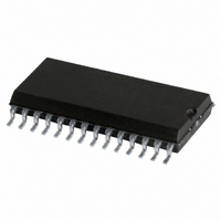
SJA1000T/N1,112 NXP Semiconductors, SJA1000T/N1,112 Datasheet - Page 50

SJA1000T/N1,112
Manufacturer Part Number
SJA1000T/N1,112
Description
IC STAND-ALONE CAN CTRLR 28-SOIC
Manufacturer
NXP Semiconductors
Datasheet
1.SJA1000TN1112.pdf
(68 pages)
Specifications of SJA1000T/N1,112
Package / Case
28-SOIC (7.5mm Width)
Controller Type
CAN Interface
Interface
CAN
Voltage - Supply
4.5 V ~ 5.5 V
Current - Supply
15mA
Operating Temperature
-40°C ~ 125°C
Mounting Type
Surface Mount
Product
Controller Area Network (CAN)
Number Of Transceivers
1
Data Rate
1 Mbps
Supply Voltage (max)
5.5 V
Supply Voltage (min)
4.5 V
Supply Current (max)
15 mA
Maximum Operating Temperature
+ 125 C
Minimum Operating Temperature
- 40 C
Mounting Style
SMD/SMT
Lead Free Status / RoHS Status
Lead free / RoHS Compliant
Lead Free Status / RoHS Status
Lead free / RoHS Compliant, Lead free / RoHS Compliant
Other names
568-3994-5
935230920112
SJA1000TD
SJA1000TD
935230920112
SJA1000TD
SJA1000TD
Philips Semiconductors
6.5
6.5.1
The contents of the bus timing register 0 defines the values of the Baud Rate Prescaler (BRP) and the Synchronization
Jump Width (SJW). This register can be accessed (read/write) if the reset mode is active.
In operating mode this register is read only, if the PeliCAN mode is selected. In BasicCAN mode a ‘FFH’ is reflected.
Table 44 Bit interpretation of bus timing register 0 (BTR0); CAN address 6
6.5.1.1
The period of the CAN system clock t
is calculated using the following equation:
t
where t
6.5.1.2
To compensate for phase shifts between clock oscillators of different bus controllers, any bus controller must
re-synchronize on any relevant signal edge of the current transmission. The synchronization jump width defines the
maximum number of clock cycles a bit period may be shortened or lengthened by one re-synchronization:
t
6.5.2
The contents of bus timing register 1 defines the length of the bit period, the location of the sample point and the number
of samples to be taken at each sample point. This register can be accessed (read/write) if the reset mode is active.
In operating mode, this register is read only, if the PeliCAN mode is selected. In BasicCAN mode a ‘FFH’ is reflected.
Table 45 Bit interpretation of bus timing register 1 (BTR1); CAN address 7
6.5.2.1
2000 Jan 04
scl
SJW
SAM
Stand-alone CAN controller
= 2
SJW.1
BIT 7
BIT 7
= t
SAM
BIT
Common registers
CLK
scl
B
t
B
CLK
US
US
Baud Rate Prescaler (BRP)
Synchronization Jump Width (SJW)
Sampling (SAM)
= time period of the XTAL frequency =
(2
T
T
IMING
IMING
(32
SJW.1 + SJW.0 + 1)
TSEG2.2
VALUE
SJW.0
BIT 6
BIT 6
R
R
BRP.5 + 16
1
0
EGISTER
EGISTER
triple; the bus is sampled three times; recommended for low/medium speed buses
(class A and B) where filtering spikes on the bus line is beneficial
single; the bus is sampled once; recommended for high speed buses (SAE class C)
0 (BTR0)
1 (BTR1)
TSEG2.1
BRP.5
BIT 5
BIT 5
BRP.4 + 8
scl
is programmable and determines the individual bit timing. The CAN system clock
TSEG2.0
BRP.3 + 4
BRP.4
BIT 4
BIT 4
------------ -
f
XTAL
1
50
BRP.2 + 2
TSEG1.3
BRP.3
BIT 3
BIT 3
FUNCTION
BRP.1 + BRP.0 + 1)
TSEG1.2
BRP.2
BIT 2
BIT 2
TSEG1.1
BRP.1
BIT 1
BIT 1
Product specification
SJA1000
TSEG1.0
BRP.0
BIT 0
BIT 0


