CCK-2412DF TDK Corporation, CCK-2412DF Datasheet - Page 10
CCK-2412DF
Manufacturer Part Number
CCK-2412DF
Description
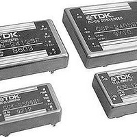
DC/DC Converters & Regulators 1.5W 24Vin +/-12V out or +/- 15Vout
Manufacturer
TDK Corporation
Series
CCKr
Datasheet
1.CCK-0512DF.pdf
(11 pages)
Specifications of CCK-2412DF
Output Power
0.72 W
Input Voltage Range
18 V to 36 V
Number Of Outputs
2
Output Voltage (channel 1)
12 V
Output Current (channel 1)
60 mA
Output Current (channel 2)
50 mA
Lead Free Status / Rohs Status
Lead free / RoHS Compliant
Available stocks
Company
Part Number
Manufacturer
Quantity
Price
Company:

Part Number:
CCK-2412DF
Manufacturer:
TDK
Quantity:
26
Company:
Part Number:
CCK-2412DF
Manufacturer:
LAMBDA
Quantity:
334


Characteristics, Functions, and Applications
TERMINAL CONNECTION
Be very careful with coupling input wires. An incorrect terminal
connection or polarity may damage a converter.
• OUTPUT VOLTAGE ADJUSTMENT TERMINAL (Vset)
The following output voltages can be outputted by connecting this
terminal to an output + or – terminal. Unless the output voltage is
adjusted, this terminal should be open.
Part No.
XX03SF
XX05SF
XX12SF
XX12DF
In addition, the voltages can be adjusted not by shorting these ter-
minals, but by connecting them to resistances as shown below.
Part No.
XX03SF
XX05SF
XX12SF
XX12DF
• Calculation formula
If the output voltage has been adjusted to be higher, it should be
noted that the output current needs to be derated so as to be suit-
able for the maximum power. If there is a possibility that a surge
voltage is applied to the output section when this product is used at
12V or ±12V, connect a capacitor of approx. 0.01 to 0.1µF
between the Vset and output GND terminals.
To improve an accuracy of the output voltage (for example, sup-
pressed to Vo±0.5% or lower), arrange the wiring as shown below
to adjust the output voltage.
• DUAL-OUTPUT CONNECTION METHOD(except CCP Type)
As for a dual-output converter, it is also possible to obtain a dou-
ble-output voltage (24V output for ±12V output) by connecting a
load between the plus and minus outputs with the GND terminal
open.
• All specifications are subject to change without notice.
Connection resistance: R(k
∗
∗
∗
∗
∗
∗
(except CCP Type)
1
2
3
4
5
6
Vo=(3.3×R+36.7)/(R+10)
Vo= 2.5×[2+2.7/(R+6.8)]
Vo=2.5+9.5 (R+10.9)/(R+8.2)
Vo=2.5+22×(R+12.7)/(R+10)[Between two outputs]
Vo=(3.3×R+36.7)/(R+12.92)
Vo=2.5×[2–2.7/(R+9.5)]
+Vout
+Vset
–Vout
Open
3.3V
5V
12V
±12V
Open
3.3V
5V
12V
±12V
Ω
–Vout connected
with resistance
3.3 to 3.67V
5 to 6
12 to 15V
±12 to ±15V
)
Variable
resistance
∗
2
–Vout shorted
3.67V
6V
15V
±15V
∗
3
∗
∗
1
4
+Vout connected
with resistance
3.3 to 2.84V
5 to 4.3V
—
—
+Vout shorted
2.84V
4.3V
—
—
∗
6
∗
5
NOISE REDUCTION
In measuring the converter noise, a value may have a significantly
large deviation according to a measuring method in case of an
inaccurate measurement. The measurement should be performed
at the base of the terminal and no loop should be made to prevent
flux from being gathered at a connection of a probe.
In addition, it should be noted that a spike voltage largely depends
upon a ripple voltmeter or a frequency band of an oscilloscope.
The TDK noise measurement is performed at the base of each ter-
minal in the 50MHz frequency band. If such significant deviation of
values is a problem, the measurement system should be reviewed.
• INPUT NOISE
This converter incorporates a filter circuit as shown below in an
input section. Therefore, it operates without any external capacitor
attached to the input section. A connection of a capacitor, how-
ever, forms
If there is a long distance from the input power supply to the input
section of the converter, connect a capacitor at the base of the
input terminal, if possible. The capacitor connected to the input
power supply portion does not have so much effect in some cases.
A long distance from the input power supply to the input section of
the converter may cause high impedance of an input line, thereby
increasing spike noise. Therefore, it is recommended to connect a
capacitor in this condition, if possible.
A capacity range of the external capacitor is approx. 0 to 470µF.
Select and connect the optimum one according to your conditions
for use.
• OUTPUT NOISE
If an output ripple is reduced, connect a capacitor of approx. 0 to
220µF to the output section of the converter. The noise is further
reduced by a connection of
tion, the filter should be of around 0 to 100µF.
To reduce output spike noise, connect a ceramic capacitor of
approx. 0 to 1µF to the output section of the converter.
If the wiring pattern between the converter output and the load is
long, the capacitor should be located at the base of the load as far
as possible. The capacitor installed close to the base of the output
of the converter may have so much effect.
Power
supply
DC-DC converter
+
–
+
π
+Vout
–
filter and reduces input return noise.
Vout
+Vin
–
DC-DC converter
Vin
+
+
π
filter as shown below. In this connec-
Load
003-01 / 20051203 / ea335_cc.fm
DC-DC converter
DC-DC converter
+Vout
–
Vout
+Vout
–
Vout
+
+
(10/11)
Load
Load
Related parts for CCK-2412DF
Image
Part Number
Description
Manufacturer
Datasheet
Request
R

Part Number:
Description:
DC/DC Converters & Regulators 1.5W 5Vin +/-12V out or +/-15Vout
Manufacturer:
TDK Corporation
Datasheet:


Part Number:
Description:
Manufacturer:
TDK Corporation
Datasheet:
Part Number:
Description:
TDK DC to DC Converters, DC to AC Inverters
Manufacturer:
TDK Corporation
Datasheet:
Part Number:
Description:
TDK DC to DC Converters, DC to AC Inverters
Manufacturer:
TDK Corporation
Datasheet: