UEI25-120-D48PM-C Murata Power Solutions Inc, UEI25-120-D48PM-C Datasheet - Page 21
UEI25-120-D48PM-C
Manufacturer Part Number
UEI25-120-D48PM-C
Description
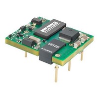
DC/DC Converters & Regulators 48V 12Vout 2.1A SMT 25.2W Pos. Polarity
Manufacturer
Murata Power Solutions Inc
Datasheet
1.UEI25-033-D48P-C.pdf
(23 pages)
Specifications of UEI25-120-D48PM-C
Product
Isolated
Output Power
25 W
Input Voltage Range
36 V to 75 V
Input Voltage (nominal)
48 V
Number Of Outputs
1
Output Voltage (channel 1)
12 V
Output Current (channel 1)
12 A
Package / Case Size
27.9 mm x 24.4 mm
Output Type
DC/DC Converter
Output Voltage
12 V
Dc / Dc Converter O/p Type
Fixed
No. Of Outputs
1
Input Voltage
36V To 75V
Power Rating
25.2W
Output Current
2.1A
Approval Bodies
CAN/CSA, EN, IEC, UL
Supply Voltage
48VDC
Lead Free Status / Rohs Status
Lead free / RoHS Compliant


maximum output voltage OR the maximum output power when setting the trim.
If the output voltage is excessive, the OVP circuit may inadvertantly shut down
the converter. If the maximum power is exceeded, the converter may enter
current limiting. If the power is exceeded for an extended period, the converter
may overheat and encounter overtemperature shut down.
input to the converter’s feedback control loop. Excessive electrical noise may
cause instability or oscillation. Keep external connections short to the Trim
input. Use shielding if needed.
Trim Equations
tor tolerances and factory-adjusted output accuracy. Mount trim resistor close
to converter. Use short leads.
Remote On/Off Control
On the input side, a remote On/Off Control can be specifi ed with either positive
or negative logic as follows:
Off pin is left open or is pulled high to +15V
bias current causes the open pin to rise to +V
disabled when the On/Off is grounded or brought to within a low voltage (see
Specifi cations) with respect to –V
grounded or brought to within a low voltage (see Specifi cations) with respect to
–V
to +15V
signal current when brought low and withstand specifi ed voltage when brought
high. Be aware too that there is a fi nite time in milliseconds (see Specifi cations)
between the time of On/Off Control activation and stable, regulated output. This
time will vary slightly with output load type and current and input conditions.
IN
CAUTION: To avoid unplanned power down cycles, do not exceed EITHER the
CAUTION: Be careful of external electrical noise. The Trim input is a senstive
Where Vo = Desired output voltage. Adjustment accuracy is subject to resis-
Positive: Models equipped with Positive Logic are enabled when the On/
Negative: Models with negative polarity are on (enabled) when the On/Off is
Dynamic control of the On/Off function should be able to sink the specifi ed
There are two CAUTIONs for the On/Off Control:
. The device is off (disabled) when the On/Off is left open or is pulled high
R
R
R
T UP
T UP
T UP
between Trim and –Vout>
DC
<Connect trim resistor
(Ω) =
(Ω) =
(Ω) =
Max. with respect to –V
Trim Up
V
V
12775
12775
25000
V
O
O
O
– 3.3
– 12
– 5
– 2050
– 2050
– 5110
UEI25-033-D48
UEI25-050-D48
UEI25-120-D48
IN
IN
.
.
R
R
R
T DOWN
T DOWN
T DOWN
DC
between Trim and +Vout>
IN
with respect to –V
<Connect trim resistor
. Positive-polarity devices are
(Ω) =
(Ω) =
(Ω) =
Trim Down
5110 x (Vo –2.5)
5110 x (Vo –2.5)
10000 (Vo-2.5)
3.3 – V
12 – V
5 – V
O
O
O
IN
www.murata-ps.com
. An internal
– 2050
– 2050
– 5110
carefully observe the voltage levels, the preferred circuit is either an open
drain/open collector transistor or a relay (which can thereupon be controlled by
logic). The On/Off prefers to be set at approx. +15V (open pin) for the ON state,
assuming positive logic.
power voltage. Otherwise the converter may be permanently damaged.
On/Off Enable Control Ground Bounce Protection
To improve reliability, if you use a small signal transistor or other external
circuit to select the Remote On/Off control, make sure to return the LO side
directly to the –Vin power input on the DC/DC converter. To avoid ground
bounce errors, do not connect the On/Off return to a distant ground plane or
current-carrying bus. If necessary, run a separate small return wire directly to
the –Vin terminal. There is very little current (typically 1-5 mA) on the On/Off
control however, large current changes on a return ground plane or ground bus
can accidentally trigger the converter on or off. If possible, mount the On/Off
transistor or other control circuit adjacent to the converter.
CAUTION: While it is possible to control the On/Off with external logic if you
CAUTION: Do not apply voltages to the On/Off pin when there is no input
Figure 5. Trim adjustments to increase Output Voltage using a Fixed Resistor
Figure 4. Trim adjustments to decrease Output Voltage using a Fixed Resistor
Figure 6. Driving the On/Off Control Pin (suggested circuit)
Single Output Isolated 25-Watt DC/DC Converters
−INPUT
−INPUT
CONTROL
+INPUT
CONTROL
+INPUT
ON/OFF
ON/OFF
-INPUT
CONTROL
+OUTPUT
−OUTPUT
+OUTPUT
−OUTPUT
ON/OFF
07 Apr 2011
TRIM
TRIM
R
TRIM UP
R
UEI25 Series
TRIM DOWN
MDC_UEI25W.A03 Page 21 of 23
+VCC
email: sales@murata-ps.com
LOAD
LOAD
Related parts for UEI25-120-D48PM-C
Image
Part Number
Description
Manufacturer
Datasheet
Request
R

Part Number:
Description:
CONV DC/DC 25W 12V
Manufacturer:
Murata Power Solutions Inc
Datasheet:

Part Number:
Description:
CONV DC/DC 12V 25W
Manufacturer:
Murata Power Solutions Inc
Datasheet:

Part Number:
Description:
DC/DC Converters & Regulators 48V 12Vout 2.1A SMT 25.2W Neg. Polarity
Manufacturer:
Murata Power Solutions Inc
Datasheet:
Part Number:
Description:
CONV DC/DC 5V 25W
Manufacturer:
Murata Power Solutions Inc
Datasheet:
Part Number:
Description:
CONV DC/DC 3.3V 25W
Manufacturer:
Murata Power Solutions Inc
Datasheet:

Part Number:
Description:
CONV DC/DC 25W 3.3V
Manufacturer:
Murata Power Solutions Inc
Datasheet:
Part Number:
Description:
CONV DC/DC 25W 5V
Manufacturer:
Murata Power Solutions Inc
Datasheet:
Part Number:
Description:
DC/DC Converters & Regulators 48V 3.3Vout 7.5A SMT 25W Pos. Polarity
Manufacturer:
Murata Power Solutions Inc
Datasheet:
Part Number:
Description:
DC/DC Converters & Regulators 48Vin 5Vout 5A SMT 25W Pos. Polarity
Manufacturer:
Murata Power Solutions Inc
Datasheet:
Part Number:
Description:
DC/DC Converters & Regulators 48V 3.3Vout 7.5A SMT 25W Neg. Polarity
Manufacturer:
Murata Power Solutions Inc
Datasheet:

Part Number:
Description:
DC/DC TH Q12-15V UEI
Manufacturer:
Murata Power Solutions Inc
Datasheet:

Part Number:
Description:
Transformers 5Vin 5Vout 200mA 4000Vdc 1:1.33 turn
Manufacturer:
Murata Power Solutions Inc
Datasheet:

Part Number:
Description:
POWER SUPPLY
Manufacturer:
Murata Power Solutions Inc
Datasheet:

Part Number:
Description:
DPM LED MINI 2VDC 3.5DIG LP RED
Manufacturer:
Murata Power Solutions Inc
Datasheet:

Part Number:
Description:
CONV DC/DC 1W 5VIN 5VOUT SIP SGL
Manufacturer:
Murata Power Solutions Inc
Datasheet: