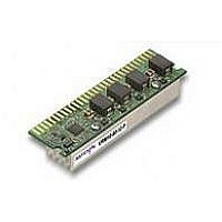
VRM10-80-12PJ Emerson Network Power, VRM10-80-12PJ Datasheet - Page 3

VRM10-80-12PJ
Manufacturer Part Number
VRM10-80-12PJ
Description
DC/DC Converters & Regulators 12VDC 0.84-1.6V 80A
Manufacturer
Emerson Network Power
Datasheet
1.VRM10-85-12-UY.pdf
(10 pages)
Specifications of VRM10-80-12PJ
Input Voltage Range
11 V to 12.6 V
Input Voltage (nominal)
12 V
Number Of Outputs
1
Output Voltage (channel 1)
0.8375 V to 1.6 V
Output Current (channel 1)
80 A
Package / Case Size
80.92 mm x 23.24 mm x 19.55 mm
Output Voltage
0.8375 V to 1.6 V
Lead Free Status / Rohs Status
Lead free / RoHS Compliant
Specifications
VRM10-85-12-UY
VRM10-85-12-UY
VRM10-85-12-UY
VRM10-80-12-PY
VRM10-105-12-EY
VRM10-105-12-EY
VRM10-105-12-EY
VRM10-105-12-EY
12 Vdc
12 Vdc
12 Vdc
Notes
1 Recommended output capacitance, 12 x 560 µF aluminium polymer and 44
2 8 mV pk-pk ripple. Vin = 12 V, Vout = 1.35 V, Iout = 85 A.
3 With the recommended capacitors (See Note 1) across the output, the
4
5 Recommended input fusing: one 20 A (or two 10 A in parallel) very fast
VOLTAGE
VRM10-85-12-UY
INPUT
x 10 µF MLCC for slew rates up to 430 A/µs, 14 x 560 µF aluminum polymer
and 45 x 10 µF MLCC for slew rates up to 930 A/µs.
output voltage stays within the load regulation window for all loads and
transient events, up to 100 A for the VRM10-85-12-UY (91 A for the VRM10-
80-12-PY) over a 20MHz bandwidth, 0 ºC < T
VRM10 uses a four phase buck topology. Each phase switches at
550 KHz for the VRM10-85-12-UY and VRM10-80-12-PY. This gives an
equivalent switching frequency of 2.2 MHz. For the VRM10-105-12-EJ, each
phase switches at 275 KHz. This gives an equivalent switching frequency of
1.1 MHz
acting fuse(s). The VRM10 is a high current device. Use appropriate
care in handling and installation of this device, which is intended only for use
within enclosed equipment.
MODEL
0.8375-1.6000 Vdc
0.8375-1.6000 Vdc
0.8375-1.6000 Vdc
VOLTAGE
OUTPUT
Table 1: LL0, LL1 Load Line Codes
N/A
LL0
0
0
1
1
0
0
1
1
N/A
LL1
0
1
0
1
0
1
0
1
OVP
1.8 V
1.8 V
1.8 V
(8)
amb
LOAD LINE SLOPE, Rout
< 60 ºC.
CURRENT
OUTPUT
(MIN)
0 A
0 A
0 A
Reserved
Reserved
1.25
1.25
1.25
1.24
1.25
1.25
1.25
CONTINUOUS
CURRENT
OUTPUT
(MAX.)
105 A
80 A
85 A
UNITS
mW
mW
mW
mW
mW
mW
mW
mW
mW
NON-SUSTAINED
6 0.01 G
7 Maximum current requires adequate forced air over the converter. Please
8 When the VRM detects an output over-voltage event, the OVP pin transitions
9 Pins 12 and 51 are not connected on VRM10-80-12-PY. On VRM10-85-12-
10 When included in the users system ESD event shall cause no out-of-
11 The ‘Y’ suffix indicates that these parts are TSE RoHS 5/6 (non Pb-free)
Hz, all axes.
consult Figures 2 and 3 for thermal de-rating.
to logic high. This signal can be used to shut down the supply to the VRM, or
drive a crowbar device.
UY , do not leave these pins floating.
regulation conditions.
compliant.
CURRENT
OUTPUT
(MAX.)
100 A
120 A
91 A
2
/Hz from 5 Hz to 20 Hz, maintaining 0.02 G
EFFICIENCY
VID = 1.325 V @ 85 A
VID = 1.325 V @ 80 A
VID = 1.325 V @ 105 A
(TYP.)
85%
85%
84%
OUTPUT VOLTAGE
Table 2: Efficiency Values
Embedded Power for
Business-Critical Continuity
See Table 1
See table 1
1.24 mV/A
REGULATION
EFFICIENCY TABLE
LOAD
2
EFFICIENCY (typ.)
/Hz from 20 Hz to 500
VRM10-105-12-EY
VRM10-85-12-UY
VRM10-80-12-PY
85%
85%
84%
NUMBER
MODEL
Rev.07.20.07
vrm10 series
(11)
(11)
(11)
3 of 10


