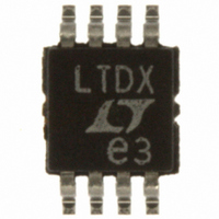
LTC1484CMS8#PBF Linear Technology, LTC1484CMS8#PBF Datasheet - Page 8

LTC1484CMS8#PBF
Manufacturer Part Number
LTC1484CMS8#PBF
Description
IC TXRX RS485 LOWPWR 8-MSOP
Manufacturer
Linear Technology
Type
Transceiverr
Datasheet
1.LTC1484CN8PBF.pdf
(16 pages)
Specifications of LTC1484CMS8#PBF
Number Of Drivers/receivers
1/1
Protocol
RS422, RS485
Voltage - Supply
4.75 V ~ 5.25 V
Mounting Type
Surface Mount
Package / Case
8-MSOP, Micro8™, 8-uMAX, 8-uSOP,
Device Type
Transceiver
Interface Type
RS422, RS485
No. Of Drivers
1
Supply Voltage Range
4.75V To 5.25V
Driver Case Style
MSOP
No. Of Pins
8
Operating Temperature Range
0°C To +70°C
Rohs Compliant
Yes
Data Rate
5Mbps
Interface Circuit Standard 1
RS-485
Number Of Receivers
1
Number Of Transmitters
1
Number Of Transceivers
1
Data Transmission Topology
Multipoint
Receiver Signal Type
Differential
Transmitter Signal Type
Differential
Single Supply Voltage (typ)
5V
Dual Supply Voltage (typ)
Not RequiredV
Dual Supply Voltage (min)
Not RequiredV
Dual Supply Voltage (max)
Not RequiredV
Supply Current
0.9mA
Power Supply Requirement
Single
Operating Temp Range
0C to 70C
Operating Temperature Classification
Commercial
Mounting
Surface Mount
Pin Count
8
Package Type
MSOP
Lead Free Status / RoHS Status
Lead free / RoHS Compliant
Available stocks
Company
Part Number
Manufacturer
Quantity
Price
LTC1484
PIN
RO (Pin 1): Receiver Output. If the receiver output is en-
abled (RE low) and the part is not in shutdown, RO is high
if (A – B) > V
also high if the receiver inputs are open or shorted to-
gether, with or without a termination resistor.
RE (Pin 2): Receiver Output Enabled. A high on this pin
three-states the receiver output (RO) and a low enables it.
DE (Pin 3): Driver Enable Input. DE = high enables the
output of the driver with the driver outputs determined by
8
TYPICAL PERFOR A CE CHARACTERISTICS
250
200
150
100
5.0
4.5
4.0
3.5
3.0
2.5
2.0
1.5
1.0
0.5
50
U
–100 –90 –80 –70 –60 –50 –40 –30 –20 –10 0
0
0
–55
Driver Output High Voltage vs
Output Current
Driver Short-Circuit Current vs
Temperature
FUNCTIONS
V
–35 –15
CC
= 4.75V
U
OUTPUT CURRENT (mA)
DRIVER OUTPUT HIGH
SHORT TO –7V
DRIVER OUTPUT LOW
SHORT TO 10V
TH(MAX)
TEMPERATURE ( C)
5
25
U
45
and low if (A – B) < V
65
V
CC
85 105 125
W
= 5.25V
1484 G31
1484 G34
U
TH(MIN)
5.0
4.5
4.0
3.5
3.0
2.5
2.0
1.5
1.0
0.5
3.0
2.5
2.0
1.5
1.0
0.5
0
0
–55
Driver Output Low Voltage vs
Output Current
0
Driver Skew vs Temperature
V
–35 –15
10 20 30 40 50 60 70 80 90 100
CC
. RO is
= 4.75V
OUTPUT CURRENT (mA)
TEMPERATURE ( C)
5
25
the DI pin. DE = low forces the driver outputs into a high
impedance state. The LTC1484 enters shutdown when
both receiver and driver outputs are disabled (RE is high
and DE is low).
DI (Pin 4): Driver Input. When the driver outputs are
enabled (DE high), DI high takes the A output high and the
B output low. DI low takes the A output low and the B
output high.
GND (Pin 5): Ground.
45
65
85 105 125
1484 G35
1484 G32
50
45
40
35
30
25
20
15
10
40
35
30
25
20
15
10
5
0
5
0
–55
4.5
Driver Propagation Delay vs
Temperature
Driver Propagation Delay vs
Supply Voltage
V
T
–35 –15
A
CC
= 25 C
= 5V
4.75
SUPPLY VOLTAGE (V)
TEMPERATURE ( C)
5
25
t
t
t
t
PHL
PLH
PHL
PLH
5
45
65
5.25
85 105 125
1484 G33
1484 G36
5.5


