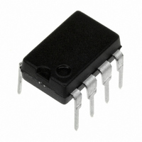
DS96176CN/NOPB National Semiconductor, DS96176CN/NOPB Datasheet

DS96176CN/NOPB
Specifications of DS96176CN/NOPB
*DS96176CN/NOPB
96176
DS96176
DS96176CN
Available stocks
Related parts for DS96176CN/NOPB
DS96176CN/NOPB Summary of contents
Page 1
... TRI-STATE ® registered trademark of National Semiconductor Corporation. © 1998 National Semiconductor Corporation DS009630 The DS96176 can be used in transmission line applications employing the DS96172 and the DS96174 quad differential line drivers and the DS96173 and DS96175 quad differential line receivers. Features n Bidirectional transceiver ...
Page 2
... Absolute Maximum Ratings If Military/Aerospace specified devices are required, please contact the National Semiconductor Sales Office/ Distributors for availability and specifications. Storage Temperature Range Molded DIP Lead Temperature Molded DIP (soldering, 10 sec.) Maximum Power Dissipation (Note 1) at 25˚C Molded Package Supply Voltage ...
Page 3
Electrical Characteristics Over recommended temperature, common mode input voltage, and supply voltage ranges, unless otherwise specified Symbol Parameter RECEIVER SECTION V Output Voltage HIGH OH V Output Voltage LOW OL I High Impedance State Output OZ I Line Input Current ...
Page 4
Receiver Switching Characteristics Note 9: Refer to EIA Standard RS-485 for exact conditions. Note 10: Only one output at a time should be shorted. Parameter Measurement Information FIGURE 1. Driver V and V OD FIGURE 4. Driver Differential Output Delay ...
Page 5
Parameter Measurement Information FIGURE 6. Driver Enable and Disable Times (t FIGURE 7. Driver Enable and Disable Times (t FIGURE 8. Receiver Propagation Delay Times (Continued) DS009630 PZH PHZ DS009630- PZL PLZ DS009630-13 5 DS009630-10 ) ...
Page 6
Parameter Measurement Information Note 11: The input pulse is supplied by a generator having the following characteristics: PRR = 1.0 MHz, 50% duty cycle, t Note 12: C includes probe and stray capacitance. L Note 13: DS96176 Driver enable is ...
Page 7
Typical Performance Characteristics Driver Differential Propagation Delay Temperature CC DS009630-22 Driver Differential Rise Time Temperature CC DS009630-24 Driver Skew Temperature CC (|t –t |) PLDH PHLD Driver Differential Propagation Delay vs ...
Page 8
Typical Performance Characteristics FIGURE 11. Typical Curve Driver Propagation Delay Test Circuit FIGURE 12. Typical Curve Driver Differential Propagation Delay Timing www.national.com (Continued) DS009630-27 8 DS009630-28 ...
Page 9
Typical Performance Curves FIGURE 13. Typical Curve Driver Differential Rise and Fall Times Receiver Propagation Delay Temperature DS009630-30 Receiver Skew Temperature CC (|t –t |) PLH PHL FIGURE 14. Typical Curve Receiver Differential ...
Page 10
Typical Performance Curves FIGURE 15. Typical Curve Receiver Propagation Delay Timing www.national.com (Continued) 10 DS009630-34 ...
Page 11
11 ...
Page 12
... National Semiconductor Asia Pacific Customer Fax: +49 (0) 1 80-530 85 86 Response Group Email: europe.support@nsc.com Tel: 65-2544466 Fax: 65-2504466 Tel: +49 (0) 1 80-532 78 32 Email: sea.support@nsc.com Tel: +49 (0) 1 80-534 16 80 National Semiconductor Japan Ltd. Tel: 81-3-5620-6175 Fax: 81-3-5620-6179 ...


