DP83848IVV/NOPB National Semiconductor, DP83848IVV/NOPB Datasheet - Page 32
DP83848IVV/NOPB
Manufacturer Part Number
DP83848IVV/NOPB
Description
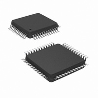
IC TXRX ETHERNET PHYTER 48-LQFP
Manufacturer
National Semiconductor
Type
Transceiverr
Datasheet
1.DP83848IVVNOPB.pdf
(84 pages)
Specifications of DP83848IVV/NOPB
Number Of Drivers/receivers
1/1
Protocol
Ethernet
Voltage - Supply
3 V ~ 3.6 V
Mounting Type
Surface Mount
Package / Case
48-LQFP
For Use With
POEPHYTEREV-I - BOARD EVAL LM5072, DP83848IPOEPHYTEREV-E - BOARD EVAL LM5072, DP83848IDP83848I-POE-EK - BOARD EVALUATION DP83848IDP83848I-MAU-EK - BOARD EVALUATION DP83848I
Lead Free Status / RoHS Status
Lead free / RoHS Compliant
Other names
*DP83848IVV
*DP83848IVV/NOPB
DP83848IVV
DP83848IVVNOPB
DP83848IVVNOPB
DP83848IVVNOPBTR
DP83848IVVNOPBTR
*DP83848IVV/NOPB
DP83848IVV
DP83848IVVNOPB
DP83848IVVNOPB
DP83848IVVNOPBTR
DP83848IVVNOPBTR
Available stocks
Company
Part Number
Manufacturer
Quantity
Price
Company:

Part Number:
DP83848IVV/NOPB
Manufacturer:
TI
Quantity:
17 200
Company:
Part Number:
DP83848IVV/NOPB
Manufacturer:
NS
Quantity:
6 125
Company:
Part Number:
DP83848IVV/NOPB
Manufacturer:
Texas Instruments
Quantity:
10 000
Part Number:
DP83848IVV/NOPB
Manufacturer:
TI/德州仪器
Quantity:
20 000


www.national.com
4.3.6 Jabber Function
The jabber function monitors the DP83848I's output and
disables the transmitter if it attempts to transmit a packet of
longer than legal size. A jabber timer monitors the transmit-
ter and disables the transmission if the transmitter is active
for approximately 85 ms.
Once disabled by the Jabber function, the transmitter stays
disabled for the entire time that the ENDEC module's inter-
nal transmit enable is asserted. This signal has to be de-
asserted for approximately 500 ms (the “unjab” time)
before the Jabber function re-enables the transmit outputs.
The Jabber function is only relevant in 10BASE-T mode.
4.3.7 Automatic Link Polarity Detection and Correction
The DP83848I's 10BASE-T transceiver module incorpo-
rates an automatic link polarity detection circuit. When
three consecutive inverted link pulses are received, bad
polarity is reported.
A polarity reversal can be caused by a wiring error at either
end of the cable, usually at the Main Distribution Frame
(MDF) or patch panel in the wiring closet.
The bad polarity condition is latched in the 10BTSCR regis-
ter. The DP83848I's 10BASE-T transceiver module cor-
rects for this error internally and will continue to decode
received data correctly. This eliminates the need to correct
the wiring error immediately.
32
4.3.8 Transmit and Receive Filtering
External 10BASE-T filters are not required when using the
DP83848I, as the required signal conditioning is integrated
into the device.
Only isolation transformers and impedance matching resis-
tors are required for the 10BASE-T transmit and receive
interface. The internal transmit filtering ensures that all the
harmonics in the transmit signal are attenuated by at least
30 dB.
4.3.9 Transmitter
The encoder begins operation when the Transmit Enable
input (TX_EN) goes high and converts NRZ data to pre-
emphasized Manchester data for the transceiver. For the
duration of TX_EN, the serialized Transmit Data (TXD) is
encoded for the transmit-driver pair (PMD Output Pair).
TXD must be valid on the rising edge of Transmit Clock
(TX_CLK). Transmission ends when TX_EN deasserts.
The last transition is always positive; it occurs at the center
of the bit cell if the last bit is a one, or at the end of the bit
cell if the last bit is a zero.
4.3.10 Receiver
The decoder detects the end of a frame when no additional
mid-bit transitions are detected. Within one and a half bit
times after the last bit, carrier sense is de-asserted.
Receive clock stays active for five more bit times after CRS
goes low, to guarantee the receive timings of the controller.
Related parts for DP83848IVV/NOPB
Image
Part Number
Description
Manufacturer
Datasheet
Request
R

Part Number:
Description:
BOARD EVALUATION DP83848I
Manufacturer:
National Semiconductor
Datasheet:
Part Number:
Description:
BOARD EVALUATION DP83848I
Manufacturer:
National Semiconductor
Datasheet:
Part Number:
Description:
EVAL BOARD PHYTER IND TEMP
Manufacturer:
National Semiconductor
Datasheet:
Part Number:
Description:
National Semiconductor [8-Bit D/A Converter]
Manufacturer:
National Semiconductor
Datasheet:
Part Number:
Description:
National Semiconductor [Media Coprocessor]
Manufacturer:
National Semiconductor
Datasheet:
Part Number:
Description:
Digitally Controlled Tone and Volume Circuit with Stereo Audio Power Amplifier, Microphone Preamp Stage and National 3D Sound
Manufacturer:
National Semiconductor
Datasheet:
Part Number:
Description:
Digitally Controlled Tone and Volume Circuit with Stereo Audio Power Amplifier, Microphone Preamp Stage and National 3D Sound
Manufacturer:
National Semiconductor
Datasheet:
Part Number:
Description:
AC97 Rev 2 Codec with Sample Rate Conversion and National 3D Sound
Manufacturer:
National Semiconductor
Part Number:
Description:
Manufacturer:
National Semiconductor
Datasheet:
Part Number:
Description:
Manufacturer:
National Semiconductor
Datasheet:
Part Number:
Description:
General Purpose, Low Voltage, Low Power, Rail-to-Rail Output Operational Amplifiers
Manufacturer:
National Semiconductor
Datasheet:
Part Number:
Description:
8-bit 20 MSPS flash A/D converter.
Manufacturer:
National Semiconductor
Datasheet:
Part Number:
Description:
Low Noise Quad Operational Amplifier
Manufacturer:
National Semiconductor
Datasheet:
Part Number:
Description:
Quad Differential Line Receivers
Manufacturer:
National Semiconductor
Datasheet: