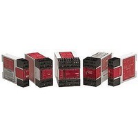
EM-T-7A BANNER ENGINEERING, EM-T-7A Datasheet - Page 6

EM-T-7A
Manufacturer Part Number
EM-T-7A
Description
Extension Module; Relay; Red LED; 24; DIN Rail; UL listed
Manufacturer
BANNER ENGINEERING
Specifications of EM-T-7A
Light Source
Red LED
Mounting
DIN Rail
Output Type
Relay
Standards
UL listed
Voltage, Supply
24 VAC⁄VDC
Coil Voltage Vdc Nom
24V
Contact Current Max
6A
Contact Voltage Ac Nom
250V
Contact Voltage Dc Nom
250V
Contact Configuration
DPDT-NO
No. Of Poles
2
Relay Mounting
DIN Rail
External Height
84mm
Lead Free Status / Rohs Status
RoHS Exempt Product
Extension Module –
Figure 4. Generalized EM-T-7A Hookup for Two-Channel Control
Two-Channel Control (Figure 4)
Two-channel control allows the Primary Safety Device to detect an unsafe failure of the
control wires. Two-channel control should be used whenever unsafe failure of the
control wires cannot be eliminated.
The outputs of the Primary Safety Device must each be normally open, forced-guided
contacts from redundant safety relays. These contacts must be monitored for failure by
the Primary Safety Device. In addition, a single contact failure cannot prevent normal
stopping action, and a successive cycle cannot be initiated until the failure has been
corrected.
The hookup diagrams in Figures 3 and 4 show a generic connection of the four safety
output channels of the Extension Module to Master Stop Control Elements MSC1
through MSC4. A Master Stop Control Element is defined as an electrically powered
device, external to the Extension Module, which stops the machinery being controlled
by immediate removal of electrical power to the machine and (when necessary) by
applying braking to dangerous motion (reference ANSI B11.19, section 5.2: “Stop
Control”). To achieve control reliability, two redundant MSCs are required to control
each machine hazard.
page
Connection to the Machine to be Controlled
6
EM-T-7A
*Arc Suppressors
Control Elements
(See Warning)
Master Stop
Machine
*
Machine Control Circuit
MSC1
13
14
*
V dc
+24
A1
U
MSC2
23
24
*
Y1
Y2
MSC3
33
34
*
A2
K
MSC4
43
44
MSC1
MSC Monitor Contacts
Model EM-T-7A
MSC2 MSC3 MSC4
L1
L2
V dc
NOTE:
This hookup is general in
nature. Your specific hookup
may vary significantly,
depending on the Primary
Safety Device used and the
machine control configuration.
0
Primary
Safety
Device
Monitoring Contact
Feedback Input
Monitoring Contact
Feedback Input
Banner Engineering Corp. • Minneapolis, U.S.A.
Website: http://www.baneng.com • Tel: 888.373.6767
NOTICE regarding MSCs
To achieve control reliability, two
redundant Master Stop Control
Elements (MSCs) are required to
control each machine hazard. Each
MSC must be capable of
immediately stopping the dangerous
machine motion, irrespective of the
state of the other. Some machines
offer only one primary control
element. For such machines, it is
necessary to duplicate the circuit of
the single MSC to add a second
MSC.
MSCs must offer at least one
forced-guided auxiliary contact
which is wired to the monitoring
contact feedback input of the
Primary Safety Device (see hookup
diagrams).


