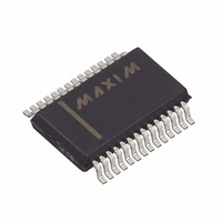
MAX3238EEAI+ Maxim Integrated Products, MAX3238EEAI+ Datasheet - Page 10

MAX3238EEAI+
Manufacturer Part Number
MAX3238EEAI+
Description
IC TXRX RS-232 TRUE 28-SSOP
Manufacturer
Maxim Integrated Products
Type
Transceiverr
Specifications of MAX3238EEAI+
Number Of Drivers/receivers
5/3
Protocol
RS232
Voltage - Supply
3 V ~ 5.5 V
Mounting Type
Surface Mount
Package / Case
28-SSOP
Propagation Delay Time Ns
0.15 us
Operating Supply Voltage
3 V to 5.5 V
Supply Current
0.5 mA
Operating Temperature Range
- 40 C to + 85 C
Data Rate
250 Kbps
Mounting Style
SMD/SMT
Lead Free Status / RoHS Status
Lead free / RoHS Compliant
+3.0V to +5.5V, 10nA, 250kbps RS-232 Transceivers
with ±15kV ESD-Protected I/O and Logic Pins
Therefore, the Machine Model is less relevant to the I/O
ports than the Human Body Model and IEC 1000-4-2.
The capacitor type used for C1–C4 is not critical for
proper operation; polarized or nonpolarized capacitors
can be used. The charge pump requires 0.1µF capaci-
tors for 3.3V operation. For other supply voltages, see
Table 3 for required capacitor values. Do not use val-
ues smaller than those listed in Table 3. Increasing the
capacitor values (e.g., by a factor of 2) reduces ripple
on the transmitter outputs and slightly reduces power
consumption. C2, C3, and C4 can be increased without
changing C1’s value. However, do not increase C1
without also increasing the values of C2, C3, C4,
and C
other capacitors).
Figure 5a. Human Body ESD Test Model
Figure 6a. IEC 1000-4-2 ESD Test Model
10
VOLTAGE
VOLTAGE
SOURCE
SOURCE
HIGH-
HIGH-
DC
DC
______________________________________________________________________________________
BYPASS
CHARGE-CURRENT
CHARGE-CURRENT
LIMIT RESISTOR
LIMIT RESISTOR
R
C
50MΩ to 100MΩ
R
C
1MΩ
100pF
150pF
to maintain the proper ratios (C1 to the
Applications Information
C s
C s
R
STORAGE
CAPACITOR
STORAGE
CAPACITOR
R
RESISTANCE
RESISTANCE
D
DISCHARGE
DISCHARGE
D
1500Ω
330Ω
Capacitor Selection
DEVICE
DEVICE
UNDER
UNDER
TEST
TEST
In most applications, decouple V
0.1µF capacitor. Further increasing this capacitor value
reduces power-supply ripple and enhances noise mar-
gin. Connect the bypass capacitor as close to the IC as
possible.
Figure 5b. Human Body Model Current Waveform
Figure 6b. IEC 1000-4-2 ESD Generator Current Waveform
Table 3. Required Minimum Capacitance
Values
AMPERES
tr = 0.7ns to 1ns
3.15 to 3.6
3.0 to 3.6
4.5 to 5.5
3.0 to 5.5
I
P
36.8%
V
100%
(V)
90%
10%
CC
100%
0
90%
10%
I
0
t
RL
30ns
C1, C
Power-Supply Decoupling
0.047
0.22
0.22
(µF)
CURRENT WAVEFORM
0.1
TIME
BYPASS
t
DL
60ns
I r
CC
PEAK-TO-PEAK RINGING
(NOT DRAWN TO SCALE)
to ground with a
C2, C3, C4
(µF)
0.22
0.33
0.1
1
t


