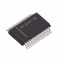
MXL1544CAI+ Maxim Integrated Products, MXL1544CAI+ Datasheet - Page 14

MXL1544CAI+
Manufacturer Part Number
MXL1544CAI+
Description
IC TXRX MULTIPROTOCOL 28-SSOP
Manufacturer
Maxim Integrated Products
Type
Transceiverr
Datasheet
1.MXL1544CAI.pdf
(20 pages)
Specifications of MXL1544CAI+
Number Of Drivers/receivers
4/4
Protocol
RS232
Voltage - Supply
5VDC
Mounting Type
Surface Mount
Package / Case
28-SSOP
Logic Family
MXL1544
Logic Type
Software Selectable Control Transceiver
Supply Voltage (max)
6 V
Supply Voltage (min)
- 0.3 V
Maximum Operating Temperature
+ 70 C
Mounting Style
SMD/SMT
Data Rate
2 Mbps
Interface
RS-232, RS-423, RS-449
Maximum Power Dissipation
889 mW
Minimum Operating Temperature
0 C
Output Current
- 50 mA to + 50 mA
Output Voltage
- 0.3 V to + 6.3 V
Supply Current
95 mA
Slew Rate
30V/µs
Supply Voltage Range
5V
Logic Case Style
SSOP
No. Of Pins
28
Operating Temperature Range
0°C To +70°C
Termination Type
SMD
Transceiver Type
Multiprotocol
Rohs Compliant
Yes
Filter Terminals
SMD
Driver Case Style
SSOP
Lead Free Status / RoHS Status
Lead free / RoHS Compliant
+5V Multiprotocol, Software-Selectable
Control Transceivers
Figure 14. V.11 Internal Resistance Networks
Figure 16 shows a port with one DB-25 connector that
can be configured for either DTE or DCE operation. The
configuration requires separate cables for proper sig-
nal routing in DTE or DCE operation. Figure 16 illus-
trates a DCE or DTE controller-selectable interface. The
DCE/DTE and INVERT inputs switch the port’s mode of
operation (Table 1).
The MXL1543 and MXL1544/MAX3175 can be connect-
ed for either DTE or DCE operation in one of two ways:
a dedicated DTE or DCE port with an appropriate gen-
der connector or a port with a connector that can be
configured for DTE or DCE operation by rerouting the
signals to the MXL1543 and MXL1544/MAX3175 using
14
A′
B′
C′
______________________________________________________________________________________
A
B
GND
S3
R8
5kΩ
30kΩ
30kΩ
R5
R4
10kΩ
R6
DTE vs. DCE Operation
R7
10kΩ
RECEIVER
MXL1544
MAX3175
a dedicated DTE cable or dedicated DCE cable. The
interface mode is selected by logic outputs from the
controller or from jumpers to either V
mode select pins. A dedicated DCE port using a DB-25
female connector is shown in Figure 17. Figure 18 illus-
trates a dedicated DTE port using a DB-25 male con-
nector.
Figure 15. V.28 Termination and Internal Resistance Network
A′
B′
C′
A
B
GND
S3
R8
5kΩ
30kΩ
30kΩ
R5
R4
10kΩ
10kΩ
R6
R7
CC
RECEIVER
MAX3175
MXL1544
or GND on the


