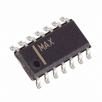
MAX1488ECSD+ Maxim Integrated Products, MAX1488ECSD+ Datasheet - Page 4

MAX1488ECSD+
Manufacturer Part Number
MAX1488ECSD+
Description
IC DVR RS232 QUAD 120KBPS 14SOIC
Manufacturer
Maxim Integrated Products
Type
Driverr
Datasheet
1.MAX1488EESD.pdf
(8 pages)
Specifications of MAX1488ECSD+
Number Of Drivers/receivers
4/0
Protocol
RS232
Voltage - Supply
4.5 V ~ 13.2 V
Mounting Type
Surface Mount
Package / Case
14-SOIC (3.9mm Width), 14-SOL
Propagation Delay Time Ns
2.8 us
Operating Supply Voltage
4.5 V to 13.2 V
Supply Current
85 uA
Operating Temperature Range
0 C to + 70 C
Data Rate
120 Kbps
Mounting Style
SMD/SMT
Number Of I/os
4 / 4
Lead Free Status / RoHS Status
Lead free / RoHS Compliant
The MAX1488E provides ±15kV of ESD protection when
operating or when powered down. After an ESD event,
the MAX1488E will not latch up. Internal slew-rate-limit-
ing circuitry eliminates the need for external capacitors.
The MAX1488E has a guaranteed 120kbps data rate.
Tables 1 and 2 describe the output states. The output
voltage level is affected by both the load current and
supply voltage, and is stable over temperature. Refer to
the Typical Operating Characteristics to see how the
output voltage varies with supply voltage, load capaci-
tance, and temperature.
Table 1. Driver A Functions
Table 2. Driver B–D Functions
The driver inputs determine the driver output states
(Tables 1 and 2). Driver inputs B, C, and D have two
inputs. Connect unused inputs to ground or V
As with all Maxim devices, ESD-protection structures
are incorporated on all pins to protect against electro-
static discharges encountered during handling and
assembly. The MAX1488E driver outputs have extra
protection against static electricity found in normal
±15kV ESD-Protected, Quad, Low-Power
RS-232 Line Driver
_____________________Pin Description
4
_______________Detailed Description
10, 12, 13
3, 6, 8, 11
2, 4, 5, 9,
_______________________________________________________________________________________
PIN
14
1
7
INPUT A
INPUT_1
H
H
X
L
L
OUTPUT_ Driver Outputs
INPUT_
NAME
GND
V
V
CC
EE
OUTPUTA
-4.5V to -13.2V Supply Voltage Input
Driver Inputs
Ground
+4.5V to +13.2V Supply Voltage Input
INPUT_2
H
H
L
X
L
±15kV ESD Protection
FUNCTION
OUTPUT_
H
H
L
Outputs
CC
Inputs
.
operation. Maxim’s engineers developed state-of-the-
art structures to protect these pins against ESD of
±15kV, without damage. After an ESD event, the
MAX1488E keeps working without latchup.
ESD protection can be tested in various ways; the
transmitter outputs are characterized for protection to
the following:
1) ±15kV using the Human Body Model
2) ±6kV using the Contact-Discharge Method specified
3) ±15kV using the Air-Gap Method specified in
ESD performance depends on a number of conditions.
Contact Maxim for a reliability report that documents
test setup, methodology, and results.
Figure 2a shows the Human Body Model, and Figure
2b shows the current waveform it generates when dis-
charged into a low impedance. This model consists of
a 100pF capacitor charged to the ESD voltage of inter-
est, which is then discharged into the test device
through a 1.5kΩ resistor.
Figure 1. Slew-Rate Test Circuit and Timing Diagram
DRIVER
V
in IEC1000-4-2 (formerly IEC801-2)
IEC1000-4-2 (formerly IEC801-2).
INPUT
GENERATOR
OUT
0V
SIGNAL
3.0V
T
1.5V
PHL
t
t
F2
F1
-3.0V
-3.3V
3.3V
3.0V
T
ESD Test Conditions
PLH
Human Body Model
R
t
t
L
R2
R1
C
L
V
V
0V
OH
OL


