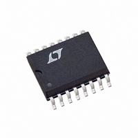
LTC489ISW#PBF Linear Technology, LTC489ISW#PBF Datasheet - Page 3

LTC489ISW#PBF
Manufacturer Part Number
LTC489ISW#PBF
Description
IC LINE RCVR RS485 QUAD 16-SOIC
Manufacturer
Linear Technology
Type
Line Receiverr
Datasheet
1.LTC488CNPBF.pdf
(12 pages)
Specifications of LTC489ISW#PBF
Number Of Drivers/receivers
0/4
Protocol
RS422, RS485
Voltage - Supply
4.75 V ~ 5.25 V
Mounting Type
Surface Mount
Package / Case
16-SOIC (0.300", 7.5mm Width)
Interface Circuit Standard 1
RS-485
Number Of Receivers
4
Number Of Transmitters
Not Required
Number Of Transceivers
Not Required
Data Transmission Topology
Multipoint
Receiver Signal Type
Differential
Transmitter Signal Type
Not Required
Single Supply Voltage (typ)
5V
Single Supply Voltage (min)
4.75V
Single Supply Voltage (max)
5.25V
Dual Supply Voltage (typ)
Not RequiredV
Dual Supply Voltage (min)
Not RequiredV
Dual Supply Voltage (max)
Not RequiredV
Supply Current
10mA
Power Supply Requirement
Single
Operating Temp Range
-40C to 85C
Operating Temperature Classification
Industrial
Mounting
Surface Mount
Pin Count
16
Package Type
SOIC W
Lead Free Status / RoHS Status
Lead free / RoHS Compliant
Available stocks
Company
Part Number
Manufacturer
Quantity
Price
ORDER INFORMATION
DC ELECTRICAL CHARACTERISTICS
temperature range, otherwise specifi cations are at T
The
V
Note 1: Stresses beyond those listed under Absolute Maximum Ratings
may cause permanent damage to the device. Exposure to any Absolute
Maximum Rating condition for extended periods may affect device
reliability and lifetime.
LEAD FREE FINISH
LTC488CN#PBF
LTC488CSW#PBF
LTC488IN#PBF
LTC488ISW#PBF
LTC489CN#PBF
LTC489CSW#PBF
LTC489IN#PBF
LTC489ISW#PBF
Consult LTC Marketing for parts specifi ed with wider operating temperature ranges.
Consult LTC Marketing for information on non-standard lead based fi nish parts.
For more information on lead free part marking, go to:
For more information on tape and reel specifi cations, go to:
SYMBOL
V
V
I
I
V
ΔV
V
V
I
I
R
I
t
t
t
SYMBOL
t
t
t
t
IN1
IN2
OZR
CC
OSR
PHL
SKD
ZH
LZ
PLH
ZL
HZ
INH
INL
TH
OH
OL
IN
CC
TH
= 5V ± 5% (Notes 2, 3), unless otherwise noted.
l
denotes the specifi cations which apply over the full operating temperature range, otherwise specifi cations are at T
PARAMETER
Input High Voltage
Input Low Voltage
Input Current
Input Current (A, B)
Differential Input Threshold Voltage for Receiver
Receiver Input Hysteresis
Receiver Output High Voltage
Receiver Output Low Voltage
Three-State Output Current at Receiver
Supply Current
Receiver Input Resistance
Receiver Short-Circuit Current
Receiver Input to Output
Receiver Input to Output
| t
Differential Receiver Skew
PARAMETER
Receiver Enable to Output Low
Receiver Enable to Output High
Receiver Disable from Low
Receiver Disable from High
PLH
– t
PHL
|
LTC488CN#TRPBF
LTC488CSW#TRPBF
LTC488IN#TRPBF
LTC488ISW#TRPBF
LTC489CN#TRPBF
LTC489CSW#TRPBF
LTC489IN#TRPBF
LTC489ISW#TRPBF
TAPE AND REEL
http://www.linear.com/leadfree/
PART MARKING
LTC488CN
LTC488CSW
LTC488IN
LTC488ISW
LTC489CN
LTC489CSW
LTC489IN
LTC489ISW
http://www.linear.com/tapeandreel/
A
= 25°C. V
CONDITIONS
EN, EN, EN12, EN34
EN, EN, EN12, EN34
EN, EN, EN12, EN34
V
V
–7V ≤ V
V
I
I
V
No Load, Digital Pins = GND or V
–7V ≤ V
0V ≤ V
C
C
C
CONDITIONS
C
C
C
C
O
O
CC
CC
CM
CC
L
L
L
L
L
L
L
= –4mA, V
= 4mA, V
CC
= 15pF (Figures 1, 3)
= 15pF (Figures 1, 3)
= 15pF (Figures 1, 3)
= 15pF (Figures 2, 4) S1 Closed
= 15pF (Figures 2, 4) S2 Closed
= 15pF (Figures 2, 4) S1 Closed
= 15pF (Figures 2, 4) S2 Closed
= 0V or 5.25V, V
= 0V or 5.25V, V
= Max 0.4V ≤ V
The
= 0V
= 5V (Notes 2, 3), unless otherwise noted.
O
CM
CM
≤ V
l
Note 2: All currents into device pins are positive; all currents out of device
pins are negative. All voltages are referenced to device ground unless
otherwise specifi ed.
Note 3: All typicals are given for V
≤ 12V
≤ 12V, V
ID
denotes the specifi cations which apply over the full operating
CC
ID
= –0.2V
PACKAGE DESCRIPTION
16-Lead Plastic DIP
16-Lead Plastic SO
16-Lead Plastic DIP
16-Lead Plastic SO
16-Lead Plastic DIP
16-Lead Plastic SO
16-Lead Plastic DIP
16-Lead Plastic SO
= 0.2V
CC
O
IN
IN
≤ 2.4V
= 0V
= 12V
= – 7V
CC
l
l
l
l
l
l
l
l
l
l
l
l
l
l
l
l
l
l
LTC488/LTC489
CC
= 5V and T
–0.2
MIN
MIN
2.0
3.5
12
12
12
7
A
TEMPERATURE RANGE
0°C to 70°C
0°C to 70°C
–40°C to 85°C
–40°C to 85°C
0°C to 70°C
0°C to 70°C
–40°C to 85°C
–40°C to 85°C
TYP
TYP
= 25°C.
60
28
28
30
30
30
30
7
4
MAX
MAX
–0.8
A
0.8
1.0
0.2
0.4
± 2
±1
10
85
55
55
60
60
60
60
= 25°C.
UNITS
UNITS
4889fb
3
mA
mA
mV
mA
mA
kΩ
μA
μA
ns
ns
ns
ns
ns
ns
ns
V
V
V
V
V


