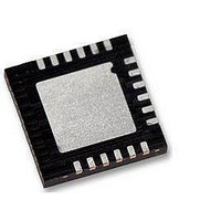
ATA6831-PIQW Atmel, ATA6831-PIQW Datasheet - Page 5

ATA6831-PIQW
Manufacturer Part Number
ATA6831-PIQW
Description
MOSFET & Power Driver ICs Triple Half-Bridge Driver
Manufacturer
Atmel
Type
High Side/Low Sider
Datasheet
1.ATA6831N-PIQW.pdf
(17 pages)
Specifications of ATA6831-PIQW
Product
Half-Bridge Drivers
Rise Time
100 ns
Fall Time
100 ns
Supply Current
6 mA
Maximum Operating Temperature
+ 150 C
Mounting Style
SMD/SMT
Package / Case
QFN-18
Bridge Type
Half Bridge
Minimum Operating Temperature
- 40 C
Number Of Drivers
3
Number Of Outputs
6
Lead Free Status / Rohs Status
Lead free / RoHS Compliant
4908I–AUTO–01/11
Bit 15 Bit 14
Bit 15
SI
H
H
H
H
Bit 14
OCS
H
H
H
H
(OCS)
Bit 13
Bit 13
OLD
H
H
H
H
Bit 12
Bit 12
PH3
H
L
L
Table 3-2.
After power-on reset, the input register has the following status:
L
The following patterns are used to enable internal test modes of the IC. Do not use these pat-
terns during normal operation.
Bit
10
11
12
13
14
15
0
1
2
3
4
5
6
7
8
9
Bit 11
Bit 11
PL3
H
L
L
L
Output (Status)
Bit 10
Bit 10
Status HS1
Status HS2
Status HS3
Status LS1
Status LS2
Status LS3
PH2
Output Data Protocol
Register
H
L
L
L
n. u.
n. u.
n. u.
n. u.
n. u.
n. u.
OVL
PSF
INH
TP
Bit 9
Bit 9
PL2
H
L
L
L
Bit 8
Bit 8
PH1
H
L
L
Function
Temperature prewarning: high = warning
Normal operation: high = output is on, low = output is off
Open-load detection: high = open load, low = no open load
(correct load condition is detected if the corresponding output is
switched off); not affected by SRR
Normal operation: high = output is on, low = output is off
Open-load detection: high = open load, low = no open load
(correct load condition is detected if the corresponding output is
switched off); not affected by SRR
Description see LS1
Description see HS1
Description see LS1
Description see HS1
Not used
Not used
Not used
Not used
Not used
Not used
Over-load detected: set high, when at least one output is switched off
by a short-circuit condition or an overtemperature event. Bits 1 to 6 can
be used to detect the affected switch
Inhibit: this bit is controlled by software (bit SI in input register)
High = standby, low = normal operation
Power-supply fail: undervoltage at pin VS detected
L
Bit 7
Bit 7
PL1
H
L
L
L
(HS3)
Bit 6
Bit 6
HS3
L
L
L
L
(LS3)
Bit 5
Bit 5
LS3
L
L
L
L
(HS2)
Bit 4
Bit 4
HS2
L
L
L
L
Atmel ATA6831
(LS2)
Bit 3
Bit 3
LS2
L
L
L
L
(HS1)
Bit 2
Bit 2
HS1
L
L
L
L
(LS1)
Bit 1
Bit 1
LS1
L
L
L
L
(SRR)
Bit 0
Bit 0
SRR
L
L
L
L
5


