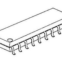
NJM3770AE2-TE2 NJR, NJM3770AE2-TE2 Datasheet - Page 8

NJM3770AE2-TE2
Manufacturer Part Number
NJM3770AE2-TE2
Description
Motor / Motion / Ignition Controllers & Drivers Stepping Motor Driver
Manufacturer
NJR
Type
Stepper Motor Controller/Driverr
Datasheet
1.NJM3770AD3.pdf
(10 pages)
Specifications of NJM3770AE2-TE2
Product
Stepper Motor Controllers / Drivers
Operating Supply Voltage
10 V to 45 V
Supply Current
30 mA to 40 mA
Mounting Style
SMD/SMT
Package / Case
EMP-20
Operating Temperature
- 40 C to + 150 C
Lead Free Status / Rohs Status
Lead free / RoHS Compliant
Analog control
As the current levels can be continuously controlled by modulating the V
achieved.
Sensor resistor
The R
choice for 800 mA max motor current at V
i
External recirculation diodes
Recirculation diodes must be connected across each motor terminal and the supply voltage, V
be connected to the motor terminals and the cathodes to the V
used for maximum performance and reliability.
Figure 8. Copper foil used as a heatsink
m
90
80
70
60
50
40
30
The peak motor current, i
= (V
Thermal resistance [ C/W]
PLCC package
DIP package
S
R
5
resistor should be of a noninductive type power resistor. A 0.5 ohm resistor, tolerance
• 0.080) / R
PCB copper foil area [cm ]
10
15
20
S
[A], at 100% level
25
2
30
m
, can be calculated by using the formula:
35
R
16-pin
28-pin
PLCC
= 5V.
20-pin
DIP
EMP
Figure 9. Principal operating sequence.
Half step position
Full step position
–100%
–100%
–20%
100%
–60%
100%
–60%
MM
20%
60%
60%
Ph
Ph
I
I
I
I
I
I
0A
1A
0B
1B
MA
MB
A
B
voltage. Ultra-fast recovery diodes should be
Stand by mode
at 20 %
R
input, limited microstepping can be
Half step mode at 100 %
NJM3770A
MM
1%, is a good
. The anodes shall
Full step mode at 60 %


