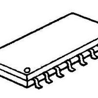
NJM2611M-TE1 NJR, NJM2611M-TE1 Datasheet

NJM2611M-TE1
Specifications of NJM2611M-TE1
Related parts for NJM2611M-TE1
NJM2611M-TE1 Summary of contents
Page 1
... Wide Operating Voltage ● Setting up the dead band by the internal constant ● Internal Output NPN Power Transistor ● Internal Constant Voltage Circuit ● Package Outline ● Bipolar Technology ■ BLOCK DIAGRAM Ver.2003-12-09 SERVO MOTOR CONTROLLER DIP16, DMP16 NJM2611D / M ■ PACKAGE OUTLINE NJM2611D NJM2611M - 1 - ...
Page 2
ABSOLUTE MAXIMUM RATINGS PARAMETER Supply Voltage Power Dissipation Output Sink Current Operating Temperature Range Storage Temperature Range (note) Due to the pulse driving, the peak current must be maintained within the range of the maximum ratings. ■ ELECTRICAL CHARACTERISTICS ...
Page 3
PIN DESCRIPTION PIN NO. PIN FUNCTION 1 V Input the positive pulse of more than 1.85V Constant output voltage of 1.25V (typical). Through REF the resistor which is connected to this pin, and setting up the ...
Page 4
PIN NO. PIN FUNCTION 3 V Connect the resistors along to the motor reg inter-locking potentiometer pulse stretcher. Connect the capacitor of more than 0.1µF. 4 PS1 Connect the resistor between Vref. The pulse gain can be decided by this ...
Page 5
PIN NO. PIN FUNCTION 6 PSV Nomally, this pin is used on the open state of operation. Especially, when it is reguired to make the adjustment of the dead band, connect the resistor between GND and then the dead band ...
Page 6
PIN NO. PIN FUNCTION 11 OUT1 Connect the collector of the external PNP transistor, the base of which is connected to pin 9. Connect the motor between pin 13. 12 PNP2 Connect the external PNP transistor (Q1) base. 13 OUT2 ...
Page 7
PIN NO. PIN FUNCTION 14 C Connect the sawtooth wave generating capacitor. P The motor's position shall be decided at the peak point of sawtooth wave, so that it is advisabled to select the higher precision capacitor as well as ...
Page 8
TYPICAL APPLICATION Notes ( Potentiometer coupled mechanically to the servo motor 1 ( Adjusting the motor center location 2 (3) Hunching prevention 0.01µF Capacitor between pin 11 and GND 0.01µF Capacitor between pin 13 and ...
Page 9
TYPICAL CHARACTERISTICS Operating Current vs. Operating Voltage Regulator Voltage vs. Operating Voltage Ver.2003-12-09 Dead Band Pin 6 Voltage vs. Pin 6 Sink Current Regulator Voltage vs. Temperature [CAUTION] The specifications on this databook are only given for information , ...


