DLP-2232H DLP Design Inc, DLP-2232H Datasheet - Page 9
DLP-2232H
Manufacturer Part Number
DLP-2232H
Description
Interface Modules & Development Tools Dual Ch USB Adapter w/ FTDI FT2232H
Manufacturer
DLP Design Inc
Series
-r
Datasheet
1.DLP-2232H.pdf
(17 pages)
Specifications of DLP-2232H
Interface Type
USB, I2C, JTAG, SPI, UART
Description/function
High Speed USB Adapter
Dimensions
57.8 mm x 23.5 mm
Maximum Operating Temperature
+ 85 C
Minimum Operating Temperature
- 40 C
Number Of Channels
2
Product
Interface Modules
Supply Current
75 mA
Supply Voltage (max)
5 V
Supply Voltage (min)
4 V
Main Purpose
Interface, USB 2.0 to UART (RS232) Bridge
Embedded
No
Utilized Ic / Part
FT2232H
Primary Attributes
Full Speed USB to High-Speed UART
Secondary Attributes
Royalty-Free Drivers, 2K EEPROM
Lead Free Status / Rohs Status
Lead free / RoHS Compliant


5.0 EEPROM WRITE UTILITY
The DLP-2232H has the option to accept manufacturer-specific information that is written into
EEPROM memory. Parameters that can be programmed include the VID and the PID
identifiers, the manufacturer's product string and a serial number.
MPROG is the EEPROM programming utility for the FT2232H device. You must install the
latest release of the CDM drivers in order to run this application. If you have CDM drivers
installed on the PC that is to perform the EEPROM write process, you can run MPROG and
update the EEPROM contents with either mode (VCP or D2XX) active.
6.0 QUICK START GUIDE
This guide requires the use of a Windows XP/Vista/7 PC that is equipped with a USB port.
1. Configure mode select jumpers using the shunts provided. Refer to section 2.1 on page 5.
2. Download the latest CDM device drivers from either www.dlpdesign.com or
3. Connect the DLP-2232H module to the PC via a USB ‘A’ to mini-B cable. This action
At this point, the DLP-2232H is ready for use. Note that if the DLP-2232H is configured for 245
FIFO mode that it will appear non-responsive if data sent from the host PC is not read by an
attached microcontroller, microprocessor, DSP, FPGA, ASIC, etc.
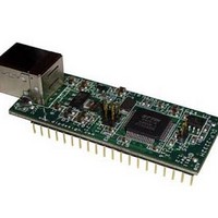
7.0 PIN LOCATIONS
Rev. 1.1 (May 2011)
www.ftdichip.com. Unzip the drivers into a folder on the hard drive.
initiates the loading of the USB drivers. When prompted, select the folder where the device
drivers were stored in Step 1. Windows will then complete the installation of the device
drivers for the DLP-2232H module. The next time the DLP-2232H module is attached, the
host PC will immediately load the correct drivers without any prompting. Reboot the PC if
prompted to do so.
Pin 20
Pin 1
(Interface Headers on bottom of PCB)
9
Top View
USB
Pin 40
Pin 21
© DLP Design, Inc.
Related parts for DLP-2232H
Image
Part Number
Description
Manufacturer
Datasheet
Request
R

Part Number:
Description:
Zigbee / 802.15.4 Modules & Development Tools USE 626-DLP-RF2-Z
Manufacturer:
DLP Design Inc
Datasheet:
Part Number:
Description:
Zigbee / 802.15.4 Modules & Development Tools TTL SERIAL INTERFACE MODULE
Manufacturer:
DLP Design Inc
Datasheet:

Part Number:
Description:
MODULE USB-TO-TTL SRL UART CONV
Manufacturer:
DLP Design Inc
Datasheet:

Part Number:
Description:
Interface Modules & Development Tools FLASH2 TARGET BOARD 18F2321 w/IDE 2k Ltd
Manufacturer:
DLP Design Inc

Part Number:
Description:
Interface Modules & Development Tools FLASH2 TARGET BOARD 16F917 w/IDE 2k Ltd
Manufacturer:
DLP Design Inc

Part Number:
Description:
Interface Modules & Development Tools FLASH2 TARGET BOARD 18F4420 w/IDE 2k Ltd
Manufacturer:
DLP Design Inc
Part Number:
Description:
Zigbee / 802.15.4 Modules & Development Tools TTL SERIAL INTERFACE MODULE
Manufacturer:
DLP Design Inc
Datasheet:

Part Number:
Description:
Interface Modules & Development Tools USB FPGA Module w/ Xilinx XC3S400A
Manufacturer:
DLP Design Inc
Datasheet:

Part Number:
Description:
MODULE DATA-ACQUISITION 8-CH
Manufacturer:
DLP Design Inc
Datasheet:

Part Number:
Description:
MODULE DATA-ACQUISITION 20-CH
Manufacturer:
DLP Design Inc
Datasheet:

Part Number:
Description:
MODULE USB-MCU FT245RL W/16F877A
Manufacturer:
DLP Design Inc
Datasheet:

Part Number:
Description:
MODULE USB-TO-FPGA TRAINING TOOL
Manufacturer:
DLP Design Inc
Datasheet:

Part Number:
Description:
MODULE USB-MCU FT232R W/18F2410
Manufacturer:
DLP Design Inc
Datasheet:

Part Number:
Description:
MODULE USB-MCU FT245RL W/SX48
Manufacturer:
DLP Design Inc
Datasheet:

Part Number:
Description:
MODULE USB-MCU FT2232D W/16F877A
Manufacturer:
DLP Design Inc
Datasheet: