N9912A-235 AGILENT TECHNOLOGIES, N9912A-235 Datasheet
N9912A-235
Specifications of N9912A-235


N9912A-235 Summary of contents
Page 1
... Agilent FieldFox N9912A 4/6 GHz Technical Overview RF Analyzer ...
Page 2
Tackle Complex Networks in Less Time FieldFox With the proliferation of wireless communications, operating frequencies have soared from sub-GHz levels up to 5.8 GHz result, service providers are required to build more base stations to cover the same ...
Page 3
World’s Most Integrated Handheld RF Analyzer FieldFox Key measurements • Cable and antenna test, distance-to fault, return loss, cable loss • Vector network analysis with Smith chart display • Vector voltmeter • Spectrum analyzer, CHP, ACPR, OBW • Interference analyzer, ...
Page 4
Task-driven Features Connector covers help keep dust out Anti-glare 6.5 inch LCD display with LED backlight Convenient side strap makes it easy to hold and carry Task-driven keys are grouped to easily and naturally perform standard fi eld measurements Portrait ...
Page 5
RF Out Connector bay protects RF connectors Easily accessible battery compartment Gasketed doors protect ports from moisture External reference and external trigger Spacious connector design makes connections fast and simple LAN port for fast SD fl ash card slot for ...
Page 6
Key Measurements FieldFox Cable and antenna analyzer Fifty to sixty percent of cell site problems are caused by faulty cables, connectors, and antennas. Degraded feed lines cause poor coverage, unnecessary handovers, paging failures, and access failures on uplink. To avoid ...
Page 7
FieldFox Measurements in the fi eld without the need to manually calibrate Each instrument is CalReady at the RF Out port, immediately following power-on or preset. This means it’s already calibrated and ready to make accurate measurements such as one-port ...
Page 8
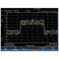
Spectrum analyzer display Interference hunting FieldFox Broadband calibration FieldFox allows you to make broadband calibrations, which means the instrument is calibrated over the maximum frequency span. After a broadband calibration, you can change the frequency range or number of points ...
Page 9
FieldFox’s Independent CW signal source Device input impedance displayed on a Smith chart FieldFox Independent signal source FieldFox has a built-in independent signal source, with a frequency range of 2 MHz to 4/6 GHz. The signal source and spectrum analyzer ...
Page 10
Transmission measurement VVM applications: • Cable trimming of phase matched cables • Verifying the isolation of 2-port components • Radio navigation – VHF omnidirectional radio range (VOR) and instrumentation landing system (ILS) FieldFox Power meter FieldFox can connect with the ...
Page 11
Feature and Benefi t Summary Perform and view return loss and distance to fault measurements at the same time Locate interference signals Waterfall display Channel power measurement Comprehensive measurement capabilities Cable and antenna Return loss/VSWR measurements allow you to evaluate ...
Page 12
Make accurate true average power measure- ments without bringing along a power meter Transfl ective display makes it easy to read measurements in direct sunlight Water resistant chassis withstands wide temperature ranges and humid environments Comprehensive measurement capabilities Power meter ...
Page 13
Specifi cations A condensed version of the specifi cations is provided here. See the User’s Guide for the complete version; Specifi cation (spec.): Warranted performance. Specifi cations include guardbands to account for the expected statistical performance distribution, measurement uncertainties, and ...
Page 14
Dynamic range Refl ection (RF Out port) 2 MHz to 4 GHz > 4 GHz to 6 GHz Transmission measurement (Option 110) 2 MHz to 2 GHz > 2 GHz to 3 GHz > 3 GHz to 5 GHz > ...
Page 15
Cable and antenna measurements Return loss Display range Resolution VSWR Display range Resolution Distance to fault (DTF) Cable loss (1-port) Insertion loss (2-ports) Transmission measurement (Option 110) Frequency range Option 104 Option 106 Dynamic range 2 MHz to 2 GHz ...
Page 16
Network analysis (Option 303) S11 S21 A R Display Calibration types IF bandwidth selections Spectrum analyzer (Option 230 or 231) Frequency Frequency range Option 104 Option 106 Frequency reference Accuracy Frequency aging Frequency reference Temperature stability Frequency readout accuracy Frequency ...
Page 17
Resolution bandwidth (RBW) Range (-3 dB bandwidth) Zero span 300 MHz in 1-3-10 sequence; 2 MHz Non-zero span 300 kHz in 1/1.5/2/3/5/7.5/10 sequence; 1 MHz, 2 MHz Accuracy 1 kHz to 1 MHz: ± ...
Page 18
Amplitude Measurement range Input attenuator range Maximum DC voltage port Maximum input power port Displayed average noise level (DANL RBW VBW, 50 ohm termination on input attenuation, average ...
Page 19
Third order intermodulation distortion (TOI) Two -30 dBm tones at input mixer, > 100 kHz tone separation < -96 dBc, +18 dBm TOI (nominal) Residual responses Input terminated attenuation, preamplifi er off, RBW ≤ 1 kHz, VBW auto-coupled ...
Page 20
Independent signal source Frequency range Amplitude High power 2 MHz to 4 GHz < +8 dBm, +6 dBm (nominal) >4 GHz to 6 GHz <+7 dBm, +2 dBm (nominal) Attenuation Functions Power meter measurement (Option 302) Frequency range USB power ...
Page 21
ESD ▪ IEC/EN 61000-4-2, functional test Safety Complies with European Low Voltage Directive 2006/95/EC • IEC/EN 61010-1 2nd Edition • Canada: CSA C22.2 No. 61010-1-04 • USA: UL 61010-1 2nd Edition Environmental Meets MIL-PRF-28800F Class 2 ...
Page 22
... External USB power sensor support Option 303 Network analysis capability Option 308 Vector voltmeter N9912A upgrades The following upgrades are available for the N9912A FieldFox RF Analyzer. More information regarding upgrades is available at: http://na.tm.agilent.com/fieldfox Product number before upgrade Description N9912AU-110 Add transmission measurement capability. ...
Page 23
... AC/DC adapter N9910X-874 External bias-tee, 2.5 MHz to 6 GHz 0.5 A N9910X-875 DC car charger and adapter N9910X-880 Extra soft carrying case with backpack and shoulder strap N9910X-881 Hard transit case N9910X-884 Extra N9912A shoulder strap For more information go to: www.agilent.com/find/fieldfox 23 23 FieldFox ...
Page 24
FieldFox Accessories Confi guration Information Directional antenna, N9910X-820 Antenna, N9910X-821 100 Watt attenuator, N9910X-860 N9910X-800 Bias-tees, N9910X-874 Phase stable cable, N9910X-810 Adapter kit, N9910X-845 T-Cal kits N9910X-801 N9910X-802 24 24 FieldFox FieldFox External battery charger, N9910X-872 AC/DC adapter, N9910X-873 DC ...
Page 25
... Soft carrying case with backpack and shoulder straps included with a standard N9912A shoul sh For an extra soft carrying case order N9910X-880 Hard transit case, N9910X-881 FieldFox fi ts inside hard transit case FieldFox oulder der st strap raps i s incl nclude uded w d with ...
Page 26
... For more information on Agilent Technologies’ products, applications or services, please con- tact your local Agilent office. The complete list is available at: www.agilent.com/find/contactus Americas Canada (877) 894 4414 ...