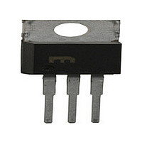
TIPL790-S Bourns Inc., TIPL790-S Datasheet - Page 2

TIPL790-S
Manufacturer Part Number
TIPL790-S
Description
Manufacturer
Bourns Inc.
Datasheet
1.TIPL790-S.pdf
(6 pages)
Specifications of TIPL790-S
Polarity
NPN
Number Of Elements
1
Collector-emitter Voltage
120V
Collector-base Voltage
150V
Emitter-base Voltage
8V
Collector Current (dc) (max)
10A
Dc Current Gain
60@0.5A@5V
Operating Temp Range
-65C to 150C
Operating Temperature Classification
Military
Mounting
Through Hole
Pin Count
3 +Tab
Package Type
TO-220
Lead Free Status / Rohs Status
Compliant
TIPL790, TIPL790A
NPN SILICON POWER DARLINGTONS
electrical characteristics at 25°C case temperature (unless otherwise noted)
NOTES: 2. Inductive loop switching measurement.
thermal characteristics
inductive-load-switching characteristics at 25°C case temperature (unless otherwise noted)
†
2
V
Voltage and current values shown are nominal; exact values vary slightly with transistor parameters.
V
V
CEO(sus)
V
R
I
I
CE(sat)
BE(sat)
I
I
V
h
C
CES
CEV
CEO
EBO
t
CBO
t
t
θJC
t
t
xo
FE
EC
f
rv
si
ob
fi
ti
t
3. These parameters must be measured using pulse techniques, t
4. These parameters must be measured using voltage-sensing contacts, separate from the current carrying contacts.
5. To obtain f
PARAMETER
PARAMETER
Junction to case thermal resistance
Current storage time
Voltage rise time
Current fall time
Current tail time
Cross over time
Collector-emitter
sustaining voltage
Collector-base
breakdown voltage
Collector-emitter
cut-off current
Collector cut-off
current
Collector cut-off
current
Emitter cut-off
current
Forward current
transfer ratio
Collector-emitter
saturation voltage
Base-emitter
saturation voltage
Parallel diode
forward voltage
Current gain
bandwidth product
Output capacitance
t
the [h
FE
] response is extrapolated at the rate of -6 dB per octave from f = 1 MHz to the frequency at which [h
I
I
V
V
V
V
V
V
V
V
V
V
I
I
I
I
I
I
I
I
I
V
V
I
I
C
C
B
B
B
B
B
B
B
B
E
C
B(off)
CE
CE
CE
CE
CE
CE
CE
CE
EB
CE
CE
CB
=
=
=
=
=
=
=
=
=
= 100 mA
=
= 10 A
= 150 V
= 200 V
= 150 V
= 200 V
= 150 V
= 200 V
= 120 V
= 150 V
=
=
=
=
= -2.5 A
20 mA
30 mA
50 mA
50 mA
20 mA
30 mA
50 mA
50 mA
1 mA
10 A
10 V
20 V
5 V
PARAMETER
5 V
L = 25 mH
V
V
V
V
1.5 < V
I
I
I
I
I
I
I
I
I
I
I
I
I
I
I
B
B
C
C
C
C
C
C
C
C
C
C
B
C
E
BE
BE
BE
BE
= 0
= 0
= 0
= 0
= 0
= 0.5 A
=
=
= 10 A
= 10 A
=
=
= 10 A
= 10 A
= 0.5 A
= 0
= 0
= 0
= 0
TEST CONDITIONS
I
V
TEST CONDITIONS
B(on)
4 A
7 A
4 A
7 A
BE(off)
EB
<8 V
= 50 mA
= -5 V
(see Note 2)
(see Note 3)
T
T
(see Notes 3 and 4)
(see Notes 3 and 4)
T
(see Notes 3 and 4)
T
f =
f = 0.1 MHz
C
C
C
C
p
= 100°C
= 100°C
= 100°C
= 100°C
= 300 µs, duty cycle ≤ 2%.
1 MHz
†
R O D U C T
(see Figures 1 and 2)
Specifications are subject to change without notice.
TIPL790
TIPL790A
TIPL790
TIPL790A
TIPL790
TIPL790A
TIPL790
TIPL790A
TIPL790
TIPL790A
TIPL790
TIPL790A
(see Note 5)
AUGUST 1978 - REVISED SEPTEMBER 2002
I N F O R M A T I O N
MIN
MIN
MIN
120
150
150
200
60
TYP
TYP
TYP
450
160
250
280
320
10
90
MAX
MAX
MAX
0.05
0.05
1.79
500
700
750
400
450
500
1.2
1.5
2.0
2.0
1.8
1.9
2.2
2.1
50
50
50
50
1
1
4
3
FE
] = 1.
°C/W
UNIT
UNIT
UNIT
MHz
mA
mA
µA
µA
pF
ns
ns
ns
ns
ns
V
V
V
V
V


