LZ4-41R100 LedEngin, LZ4-41R100 Datasheet - Page 5
LZ4-41R100
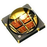
Manufacturer Part Number
LZ4-41R100
Description
LED High Power (> 0.5 Watts) Red 623nm
Manufacturer
LedEngin
Datasheet
1.LZ4-00R110.pdf
(12 pages)
Specifications of LZ4-41R100
Rohs Compliant
Yes
Luminous Flux @ Test
350lm
Wavelength Typ
625nm
Forward Current @ Test
700mA
Supply Voltage
9.7V
Power Module Configuration
Square
Power Rating
10W
Led Module Type
Board + LED
Lead Free Status / Rohs Status
Details


Notes for Table 5:
1.
2:
3.
4.
5.
6.
Notes for Table 6:
1.
2.
3.
Notes for Table 7:
1.
LedEngin,
Maximum DC forward current (per die) is determined by the overall thermal resistance and ambient temperature.
Follow the curves in Figure 10 for current derating.
Pulse forward current conditions: Pulse Width ≤ 10msec and Duty Cycle ≤ 10%.
LEDs are not designed to be reverse biased.
Solder conditions per JEDEC 020D. See Reflow Soldering Profile Figure 3.
Autoclave Conditions per JEDEC JESD22-A102-C.
LedEngin recommends taking reasonable precautions towards possible ESD damages and handling the LZ4-00R110
in an electrostatic protected area (EPA). An EPA may be adequately protected by ESD controls as outlined in
ANSI/ESD S6.1.
Luminous flux typical value is for all four LED dice operating concurrently at rated current.
Viewing Angle is the off axis angle from emitter centerline where the luminous intensity is ½ of the peak value.
Total Included Angle is the total angle that includes 90% of the total luminous flux.
Forward Voltage typical value is for all four LED dice connected in series.
Peak Pulsed Forward Current
Forward Voltage (@ I
Soldering Temperature
Allowable Reflow Cycles
Forward Voltage (@ I
Luminous Flux (@ I
Luminous Flux (@ I
Autoclave Conditions
DC Forward Current
Junction Temperature
Luminous Flux (@ I
Storage Temperature
Radiant Flux (@ I
ESD Sensitivity
Reverse Voltage
Temperature Coefficient
Inc.
Dominant Wavelength
Total Included Angle
Parameter
of Forward Voltage
Thermal Resistance
(Junction to Case)
Viewing Angle
Parameter
Parameter
Electrical Characteristics @ T
Optical Characteristics @ T
[6]
F
F
F
Absolute Maximum Ratings
F
F
= 1000mA)
= 1500mA)
F
[1]
= 700mA)
[5]
= 700mA)
= 1000mA)
[4]
= 700mA)
[2]
[1]
[2]
[3]
[1]
[1]
[1]
[1]
[1]
Table 5:
Table 6:
Table 7:
Symbol
5
T
T
Symbol
Symbol
∆V
I
V
T
I
FP
stg
F
sol
RΘ
2Θ
R
Θ
J
Φ
Φ
Φ
λ
V
V
F
Φ
0.9V
/∆T
D
F
F
V
V
V
1/2
J-C
J
Class 3B JESD22-A114-D
C
100% RH for 168 hours
C
= 25°C
Typical
Typical
121°C at 2 ATM,
= 25°C
> 8,000 V HBM
10.4
350
465
625
625
100
-7.6
1.8
9.7
1.8
90
See Note 3
-40 ~ +125
Value
1000
1500
125
260
6
Degrees
Degrees
mV/°C
LZ4-00R110 (01/14/10)
°C/W
Unit
Unit
nm
lm
lm
lm
W
V
V
Unit
mA
mA
°C
°C
°C
V
Related parts for LZ4-41R100
Image
Part Number
Description
Manufacturer
Datasheet
Request
R

Part Number:
Description:
LED High Power (> 0.5 Watts) Ultraviolet 10 Watt 365 nm
Manufacturer:
LedEngin
Datasheet:

Part Number:
Description:
LED High Power (> 0.5 Watts) Ultraviolet 10 Watt 365 nm
Manufacturer:
LedEngin
Datasheet:

Part Number:
Description:
LED High Power (> 0.5 Watts) Red 10 Watt 635 nm
Manufacturer:
LedEngin
Datasheet:

Part Number:
Description:
LED High Power (> 0.5 Watts) Ultraviolet 10 Watt 400 nm
Manufacturer:
LedEngin
Datasheet:

Part Number:
Description:
LED High Power (> 0.5 Watts) Green 10 Watt 530 nm
Manufacturer:
LedEngin
Datasheet:
Part Number:
Description:
LED High Power (> 0.5 Watts) Blue 10 Watt 445-475 nm
Manufacturer:
LedEngin
Datasheet:

Part Number:
Description:
LED High Power (> 0.5 Watts) Red 10 Watt 635 nm
Manufacturer:
LedEngin
Datasheet:
Part Number:
Description:
LED High Power (> 0.5 Watts) Red 10 Watt 635 nm
Manufacturer:
LedEngin
Datasheet:

Part Number:
Description:
LED High Power (> 0.5 Watts) RGBA 10 Watt Full Color
Manufacturer:
LedEngin
Datasheet:
Part Number:
Description:
LED High Power (> 0.5 Watts) Green 10 Watt 530 nm
Manufacturer:
LedEngin
Datasheet:
Part Number:
Description:
LED High Power (> 0.5 Watts) Blue 10 Watt 445-475 nm
Manufacturer:
LedEngin
Datasheet:
Part Number:
Description:
LED High Power (> 0.5 Watts) Blue 10 Watt 445-475 nm
Manufacturer:
LedEngin
Datasheet:

Part Number:
Description:
LED High Power (> 0.5 Watts) Green 15 Watt 530 nm
Manufacturer:
LedEngin
Datasheet:
Part Number:
Description:
LED High Power (> 0.5 Watts) Deep Red 10 Watt 655-670nm
Manufacturer:
LedEngin
Datasheet:

Part Number:
Description:
LED High Power (> 0.5 Watts) Warm White 10 Watt 2870-3700K
Manufacturer:
LedEngin
Datasheet: