LZ4-00B200 LedEngin, LZ4-00B200 Datasheet - Page 5
LZ4-00B200
Manufacturer Part Number
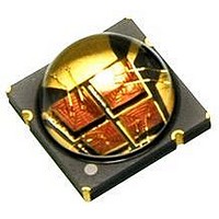
LZ4-00B200
Description
LED High Power (> 0.5 Watts) Blue
Manufacturer
LedEngin
Datasheet
1.LZ4-00B210.pdf
(12 pages)
Specifications of LZ4-00B200
Rohs Compliant
Yes
Led Color
Blue
Luminous Flux @ Test
170lm
Wavelength Typ
465nm
Forward Current @ Test
1A
Forward Current If Max
1.5A
Forward Voltage @ Test
14.6V
Power Dissipation Pd
10W
Lead Free Status / Rohs Status
Details


Notes for Table 5:
1.
2:
3.
4.
5.
6.
Notes for Table 6:
1.
2.
3.
4.
Notes for Table 7:
1.
LedEngin,
Maximum DC forward current (per die) is determined by the overall thermal resistance and ambient temperature.
Follow the curves in Figure 10 for current derating.
Pulse forward current conditions: Pulse Width ≤ 10msec and Duty Cycle ≤ 10%.
LEDs are not designed to be reverse biased.
Solder conditions per JEDEC 020D. See Reflow Soldering Profile Figure 3.
Autoclave Conditions per JEDEC JESD22-A102-C.
LedEngin recommends taking reasonable precautions towards possible ESD damages and handling the LZ4-00B210
in an electrostatic protected area (EPA). An EPA may be adequately protected by ESD controls as outlined in
ANSI/ESD S6.1.
Luminous flux typical value is for all four LED dice operating concurrently at rated current.
Observe IEC 60825-1 class 2 rating for eye safety. Do not stare into the beam.
Viewing Angle is the off axis angle from emitter centerline where the luminous intensity is ½ of the peak value.
Total Included Angle is the total angle that includes 90% of the total luminous flux.
Forward Voltage typical value is for all four LED dice connected in series.
Peak Pulsed Forward Current
Dominant Wavelength (@ I
Forward Voltage (@ I
Soldering Temperature
Allowable Reflow Cycles
Forward Voltage (@ I
Luminous Flux (@ I
Luminous Flux (@ I
Autoclave Conditions
DC Forward Current
Junction Temperature
Luminous Flux (@ I
Storage Temperature
Radiant Flux (@ I
ESD Sensitivity
Reverse Voltage
Temperature Coefficient
Inc.
Total Included Angle
Parameter
of Forward Voltage
Thermal Resistance
(Junction to Case)
Viewing Angle
Parameter
Parameter
Electrical Characteristics @ T
Optical Characteristics @ T
[6]
F
F
F
Absolute Maximum Ratings
F
F
= 1000mA)
= 1500mA)
F
[1]
= 700mA)
[5]
= 700mA)
= 1000mA)
[4]
= 700mA)
[3]
F
= 700mA)
[1]
[2]
[4]
[1]
[1]
[1]
[1]
[1]
[2]
Table 5:
Table 6:
Table 7:
Symbol
5
T
T
Symbol
Symbol
∆V
I
V
T
I
FP
stg
F
sol
RΘ
R
J
2Θ
Θ
Φ
Φ
Φ
λ
V
V
F
Φ
0.9
/∆T
D
F
F
V
V
V
J-C
½
J
Class 3B JESD22-A114-D
C
100% RH for 168 hours
C
= 25°C
Typical
Typical
121°C at 2 ATM,
= 25°C
> 8,000 V HBM
-11.6
14.0
14.6
130
170
215
465
110
120
3.0
1.8
See Note 3
-40 ~ +150
Value
1500
1500
150
260
6
Degrees
Degrees
mV/°C
LZ4-00B210 (01/14/10)
°C/W
Unit
Unit
nm
lm
lm
lm
W
V
V
Unit
mA
mA
°C
°C
°C
V
Related parts for LZ4-00B200
Image
Part Number
Description
Manufacturer
Datasheet
Request
R

Part Number:
Description:
LED High Power (> 0.5 Watts) Ultraviolet 10 Watt 365 nm
Manufacturer:
LedEngin
Datasheet:

Part Number:
Description:
LED High Power (> 0.5 Watts) Ultraviolet 10 Watt 365 nm
Manufacturer:
LedEngin
Datasheet:

Part Number:
Description:
LED High Power (> 0.5 Watts) Red 10 Watt 635 nm
Manufacturer:
LedEngin
Datasheet:

Part Number:
Description:
LED High Power (> 0.5 Watts) Ultraviolet 10 Watt 400 nm
Manufacturer:
LedEngin
Datasheet:

Part Number:
Description:
LED High Power (> 0.5 Watts) Green 10 Watt 530 nm
Manufacturer:
LedEngin
Datasheet:
Part Number:
Description:
LED High Power (> 0.5 Watts) Blue 10 Watt 445-475 nm
Manufacturer:
LedEngin
Datasheet:

Part Number:
Description:
LED High Power (> 0.5 Watts) Red 10 Watt 635 nm
Manufacturer:
LedEngin
Datasheet:
Part Number:
Description:
LED High Power (> 0.5 Watts) Red 10 Watt 635 nm
Manufacturer:
LedEngin
Datasheet:

Part Number:
Description:
LED High Power (> 0.5 Watts) RGBA 10 Watt Full Color
Manufacturer:
LedEngin
Datasheet:
Part Number:
Description:
LED High Power (> 0.5 Watts) Green 10 Watt 530 nm
Manufacturer:
LedEngin
Datasheet:
Part Number:
Description:
LED High Power (> 0.5 Watts) Blue 10 Watt 445-475 nm
Manufacturer:
LedEngin
Datasheet:
Part Number:
Description:
LED High Power (> 0.5 Watts) Blue 10 Watt 445-475 nm
Manufacturer:
LedEngin
Datasheet:

Part Number:
Description:
LED High Power (> 0.5 Watts) Green 15 Watt 530 nm
Manufacturer:
LedEngin
Datasheet:
Part Number:
Description:
LED High Power (> 0.5 Watts) Deep Red 10 Watt 655-670nm
Manufacturer:
LedEngin
Datasheet:

Part Number:
Description:
LED High Power (> 0.5 Watts) Warm White 10 Watt 2870-3700K
Manufacturer:
LedEngin
Datasheet: