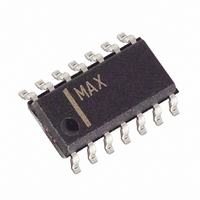
MAX3491ESD+T Maxim Integrated Products, MAX3491ESD+T Datasheet - Page 4

MAX3491ESD+T
Manufacturer Part Number
MAX3491ESD+T
Description
IC TXRX RS485/422 10MBPS 14SOIC
Manufacturer
Maxim Integrated Products
Type
Transceiverr
Datasheet
1.MAX3485CSA.pdf
(16 pages)
Specifications of MAX3491ESD+T
Number Of Drivers/receivers
1/1
Protocol
RS422, RS485
Voltage - Supply
3 V ~ 3.6 V
Mounting Type
Surface Mount
Package / Case
14-SOIC (3.9mm Width), 14-SOL
Lead Free Status / RoHS Status
Lead free / RoHS Compliant
3.3V-Powered, 10Mbps and Slew-Rate-Limited
True RS-485/RS-422 Transceivers
DRIVER SWITCHING CHARACTERISTICS—MAX3483 and MAX3488
(V
RECEIVER SWITCHING CHARACTERISTICS
(V
4
Note 1: ∆V
Note 2: Measured on
Note 3: The transceivers are put into shutdown by bringing RE high and DE low. If the inputs are in this state for less than 80ns, the
Driver Differential Output Delay
Driver Differential Output Transition Time
Driver Propagation Delay, Low-to-High Level
Driver Propagation Delay, High-to-Low Level
|
Driver Output Enable Time to Low Level
Driver Output Enable Time to High Level
Driver Output Disable Time from High Level
Driver Output Disable Time from Low Level
Driver Output Enable Time from Shutdown to Low Level
Driver Output Enable Time from Shutdown to High Level
Time to Shutdown
Receiver Propagation Delay,
Low-to-High Level
Receiver Propagation Delay,
High-to-Low Level
|
Propagation Delay Skew
Receiver Output Enable Time
to Low Level
Receiver Output Enable Time
to High Level
Receiver Output Disable
Time from High Level
Receiver Output Disable
Time from Low Level
Receiver Output Enable Time
from Shutdown to Low Level
Receiver Output Enable Time
from Shutdown to High Level
DRIVER OUTPUT ENABLE/DISABLE TIMES (MAX3483 only)
t
t
CC
PLH
CC
PLH
_______________________________________________________________________________________
= 3.3V, T
= 3.3V, T
- t
- t
PHL
PARAMETER
PHL
parts are guaranteed not to enter shutdown. If the inputs are in this state for at least 300ns, the parts are guaranteed to
have entered shutdown. See Low-Power Shutdown Mode section.
OD
|
|
Driver Propagation Delay Skew (Note 2)
Receiver
A
A
and ∆V
= +25°C)
= +25°C)
PARAMETER
OC
|
t
PLH
are the changes in V
(Y) - t
SYMBOL
t
PHL
t
t
t
t
t
t
t
t
t
SHDN
RPDS
PRZH
PRHZ
PRSH
RPLH
RPHL
PRZL
PRLZ
PRSL
(Y)
|
and
MAX3483/MAX3485/MAX3486/MAX3491 only
(Note 3)
V
MAX3483/MAX3488
V
MAX3483/MAX3488
V
MAX3483/MAX3488
C
MAX3483/MAX3485/MAX3486/MAX3491 only
C
MAX3483/MAX3485/MAX3486/MAX3491 only
C
MAX3483/MAX3485/MAX3486/MAX3491 only
C
MAX3483/MAX3485/MAX3486/MAX3491 only
C
MAX3483/MAX3485/MAX3486/MAX3491 only
C
MAX3483/MAX3485/MAX3486/MAX3491 only
ID
ID
ID
L
L
L
L
L
L
OD
|
= 15pF, Figure 12,
= 15pF, Figure 12,
= 15pF, Figure 12,
= 15pF, Figure 12,
= 15pF, Figure 12,
= 15pF, Figure 12,
t
= 0V to 3.0V, C
= 0V to 3.0V, C
= 0V to 3.0V, C
PLH
and V
(Z) - t
OC
PHL
, respectively, when the DI input changes state.
SYMBOL
CONDITIONS
(Z)
t
t
t
t
t
t
t
t
t
t
L
L
L
t
PDS
PZH
PHZ
PSH
PLH
PHL
PZL
PLZ
PSL
DD
TD
= 15pF, Figure 11
= 15pF, Figure 11
= 15pF, Figure 11
|.
R
R
R
R
R
R
R
R
R
R
R
L
L
L
L
L
L
L
L
L
L
L
= 60Ω, Figure 7
= 60Ω, Figure 7
= 27Ω, Figure 8
= 27Ω, Figure 8
= 27Ω, Figure 8
= 110Ω, Figure 10
= 110Ω, Figure 9
= 110Ω, Figure 9
= 110Ω, Figure 10
= 110Ω, Figure 10
= 110Ω, Figure 9
CONDITIONS
MIN
MIN
600
400
700
700
80
25
25
25
25
1000
1000
TYP
TYP
900
700
100
900
600
190
720
720
1.9
2.2
50
50
65
75
65
75
25
25
25
25
MAX
MAX
1400
1200
1500
1500
1300
1400
1400
800
300
120
120
2.7
3.0
80
80
90
90
10
20
50
50
45
45
UNITS
UNITS
ns
ns
ns
ns
ns
ns
ns
ns
ns
µs
µs
ns
ns
ns
ns
ns
ns
ns
ns
ns
ns


