VS-MBR1545CT-1PBF Vishay, VS-MBR1545CT-1PBF Datasheet - Page 2
VS-MBR1545CT-1PBF
Manufacturer Part Number
VS-MBR1545CT-1PBF
Description
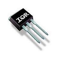
Schottky (Diodes & Rectifiers) 15 Amp 45 Volt Common Cathode
Manufacturer
Vishay
Datasheet
1.MBR1545CT-1PBF.pdf
(9 pages)
Specifications of VS-MBR1545CT-1PBF
Product
Schottky Diodes
Peak Reverse Voltage
45 V
Forward Continuous Current
15 A
Max Surge Current
150 A
Configuration
Dual Common Cathode
Forward Voltage Drop
0.84 V
Maximum Reverse Leakage Current
100 uA
Operating Temperature Range
- 65 C to + 150 C
Mounting Style
Through Hole
Package / Case
TO-262
Lead Free Status / Rohs Status
Details


MBR15..CT, MBRB15..CT, MBR15..CT-1
Bulletin PD-2.318 rev. F 01/07
Electrical Specifications
2
Voltage Ratings
Absolute Maximum Ratings
Thermal-Mechanical Specifications
I
I
E
I
V
I
C
L
dv/dt Max. Voltage Rate of Change
T
T
R
R
R
wt
T
V
V
FSM
F(AV)
AR
RM
S
AS
FM
J
stg
T
thJC
thCS
thJA
R
RWM
Parameters
Max. Aver. Forward Current (Per Leg)
Max. Peak One Cycle Non Repetitive
Non-Repetitive Avalanche Energy
Repetitive Avalanche Current
Max. Forward Voltage Drop
Max. Instantaneus Reverse Current
Max. Junction Capacitance
Typical Series Inductance
(Rated V
Parameters
Max. DC Reverse Voltage (V)
Max. Working Peak Reverse Voltage (V)
Parameters
Surge
Parameters
Max. Junction Temperature Range
Max. Storage Temperature Range
Max. Thermal Resistance Junction
to Case
Typical Thermal Resistance, Case
to Heatsink
Max. Thermal Resistance Junction
Approximate Weight
Mounting Torque
Device Marking
R
)
(Per Device)
(Per Leg)
(Per Leg)
Min.
Max.
(1)
(1)
-65 to 150
-65 to 175
2 (0.07)
Value
Value
12 (10)
Value
10000
MBR15..CT-1
MBRB15..CT
0.84
0.57
0.72
150
0.50
6 (5)
MBR15..CT
690
400
7.5
0.1
8.0
3.0
15
15
60
7
2
Kg-cm
(Ibf-in)
Units
Units
g (oz.)
Units
V/ μs
°C/W DC operation
°C/W Mounting surface, smooth and greased
°C/W DC operation
mJ
mA
mA
nH
pF
°C
°C
A
A
A
V
V
V
(Per Leg) T
Frequency limited by T
@ T
5μs Sine or 3μs Rect. pulse
Surge applied at rated load condition halfwave single
phase 60Hz
Current decaying linearly to zero in 1 μsec
@ 15A
@ 7.5A
@ 15A
T
T
V
Measured from top of terminal to mounting plane
Case style TO-220
Case style D
Case style TO-262
MBR1535CT-1
MBRB1535CT
J
J
R
MBR1535CT
= 25 °C
= 125 °C
= 5V
C
= 131 °C (Rated V
35
DC
J
(test signal range 100Khz to 1Mhz) 25°C
Conditions
Conditions
Conditions
= 25 °C, I
2
Pak
T
T
Rated DC voltage
(1) Pulse Width < 300μs, Duty Cycle <2%
J
J
= 25 °C
= 125 °C
AS
J
R
max. V
)
= 2 Amps, L = 3.5 mH
Following any rated load
condition and with rated
V
RRM
A
= 1.5 x V
MBR1545CT-1
MBRB1545CT
MBR1545CT
applied
45
www.irf.com
R
typical
Related parts for VS-MBR1545CT-1PBF
Image
Part Number
Description
Manufacturer
Datasheet
Request
R

Part Number:
Description:
357-036-542-201 CARDEDGE 36POS DL .156 BLK LOPRO
Manufacturer:
Vishay
Datasheet:
Part Number:
Description:
357-036-542-201 CARDEDGE 36POS DL .156 BLK LOPRO
Manufacturer:
Vishay
Datasheet:
Part Number:
Description:
357-036-542-201 CARDEDGE 36POS DL .156 BLK LOPRO
Manufacturer:
Vishay
Datasheet:
Part Number:
Description:
357-036-542-201 CARDEDGE 36POS DL .156 BLK LOPRO
Manufacturer:
Vishay
Datasheet:
Part Number:
Description:
357-036-542-201 CARDEDGE 36POS DL .156 BLK LOPRO
Manufacturer:
Vishay
Datasheet:
Part Number:
Description:
357-036-542-201 CARDEDGE 36POS DL .156 BLK LOPRO
Manufacturer:
Vishay
Datasheet:
Part Number:
Description:
357-036-542-201 CARDEDGE 36POS DL .156 BLK LOPRO
Manufacturer:
Vishay
Datasheet:
Part Number:
Description:
357-036-542-201 CARDEDGE 36POS DL .156 BLK LOPRO
Manufacturer:
Vishay
Datasheet:
Part Number:
Description:
357-036-542-201 CARDEDGE 36POS DL .156 BLK LOPRO
Manufacturer:
Vishay
Datasheet:
Part Number:
Description:
357-036-542-201 CARDEDGE 36POS DL .156 BLK LOPRO
Manufacturer:
Vishay
Datasheet:
Part Number:
Description:
357-036-542-201 CARDEDGE 36POS DL .156 BLK LOPRO
Manufacturer:
Vishay
Datasheet:
Part Number:
Description:
357-036-542-201 CARDEDGE 36POS DL .156 BLK LOPRO
Manufacturer:
Vishay
Datasheet:
Part Number:
Description:
357-036-542-201 CARDEDGE 36POS DL .156 BLK LOPRO
Manufacturer:
Vishay
Datasheet:
Part Number:
Description:
357-036-542-201 CARDEDGE 36POS DL .156 BLK LOPRO
Manufacturer:
Vishay
Datasheet:
Part Number:
Description:
357-036-542-201 CARDEDGE 36POS DL .156 BLK LOPRO
Manufacturer:
Vishay
Datasheet: