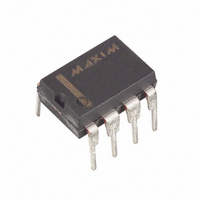
MAX253EPA+ Maxim Integrated Products, MAX253EPA+ Datasheet - Page 16

MAX253EPA+
Manufacturer Part Number
MAX253EPA+
Description
IC XFRMR DRIVER RS485 8-DIP
Manufacturer
Maxim Integrated Products
Type
Driverr
Datasheet
1.MAX253CSA.pdf
(18 pages)
Specifications of MAX253EPA+
Number Of Drivers/receivers
1/0
Protocol
RS232, RS485
Voltage - Supply
4.5 V ~ 5.5 V
Mounting Type
Through Hole
Package / Case
8-DIP (0.300", 7.62mm)
Supply Voltage (max)
6 V
Supply Voltage (min)
2.5 V
Maximum Operating Temperature
+ 85 C
Mounting Style
Through Hole
Interface
RS-485
Maximum Power Dissipation
727 mW
Minimum Operating Temperature
- 40 C
Supply Current
0.45 mA
Lead Free Status / RoHS Status
Lead free / RoHS Compliant
Transformer Driver for
Isolated RS-485 Interface
age. In addition, include in the calculations an
allowance for worst-case losses in the rectifiers. Since
the turns ratio determined in this manner will ordinarily
produce a much higher voltage at the secondary under
conditions of high input voltage and/or light loading, be
careful to prevent an overvoltage condition from occur-
ring (see Output Voltage vs. Load Current in the Typical
Operating Characteristics ).
Transformers used with the MAX253 will ordinarily be
wound on high-permeability magnetic material. To min-
imize radiated noise, use common closed-magnetic-
path physical shapes (e.g., pot cores, toroids, E/I/U
cores). A typical core is the Philips 213CT050-3B7,
which is a toroid 0.190” in diameter and 0.05” thick.
For operation with this core at 5.5V maximum supply
voltage, the primary should have approximately 22
turns on each side of the center tap, or 44 turns total.
This will result in a nominal primary inductance of
approximately 832µH. The secondary can be scaled to
produce the required DC output.
The MAX253’s high switching frequency demands
high-speed rectifiers. Schottky diodes are recom-
mended. Ensure that the Schottky diode average cur-
rent rating exceeds the load-current level. The 1N5817
Table 4. Suggested Capacitor Suppliers
16
* Nihon Inter Electronics Corp.
Surface Mount
High-Performance
Through Hole
Through Hole
USA Phone: (805) 867-2555
Japan Phone: 81-3-3494-7411
PRODUCTION METHOD
______________________________________________________________________________________
FAX: (805) 867-2556
FAX: 81-3-3494-7414
Matsuo
267 series (low ESR)
USA Phone: (714) 969-2491, FAX: (714) 960-6492
Sprague Electric Co.
595D/293D series (very low ESR)
USA Phone: (603) 224-1961, FAX: (603) 224-1430
Murata Erie
Ceramic
USA Phone: (800) 831-9172, FAX: (404) 436-3030
Sanyo
OS-CON series (very low ESR)
USA Phone: (619) 661-6835, FAX: (619) 661-1055
Japan Phone: 81-7-2070-1005, FAX: 81-7-2070-1174
Nichicon
PL series (low ESR)
USA Phone: (708) 843-7500, FAX: (708) 843-2798
Japan Phone: 81-7-5231-8461, FAX: 81-7-5256-4158
Diode Selection
CAPACITORS
is a good choice for through-hole applications, and the
NIEC* SB05W05C dual in an SOT-23 package is rec-
ommended for surface-mount applications. Use the
higher frequency setting to reduce ripple.
In applications sensitive to output-ripple noise, the out-
put filter capacitor C2 should have a low effective
series resistance (ESR), and its capacitance should
remain fairly constant over temperature. Sprague 595D
surface-mount solid tantalum capacitors and Sanyo
OS-CON through-hole capacitors are recommended
due to their extremely low ESR. Capacitor ESR usually
rises at low temperatures, but OS-CON capacitors pro-
vide very low ESR below 0°C.
In applications where output ripple is not critical, a
0.1µF chip or ceramic capacitor is sufficient. Refer to
Table 4 for suggested capacitor suppliers. Use the
higher frequency setting to reduce ripple.
The input bypass capacitor C1 is not critical. Unlike
switching regulators, the MAX253’s supply current is
fairly constant, and is therefore less dependent on the
input bypass capacitor. A low-cost 0.1µF chip or
ceramic capacitor is normally sufficient for input
bypassing.
Input Bypass Capacitor
Output Filter Capacitor


