ADDS-BF533-EZLITE Analog Devices Inc, ADDS-BF533-EZLITE Datasheet
ADDS-BF533-EZLITE
Specifications of ADDS-BF533-EZLITE


ADDS-BF533-EZLITE Summary of contents
Page 1
FEATURES Up to 600 MHz high performance Blackfin processor Two 16-bit MACs, two 40-bit ALUs, four 8-bit video ALUs, 40-bit shifter RISC-like register and instruction model for ease of pro gramming and compiler-friendly support Advanced debug, trace, and performance monitoring ...
Page 2
... UART Port ........................................................ 10 General-Purpose I/O Port F ................................... 10 Parallel Peripheral Interface ................................... 11 Dynamic Power Management ................................ 11 Voltage Regulation .............................................. 13 Clock Signals ..................................................... 13 Booting Modes ................................................... 14 Instruction Set Description ................................... 15 Development Tools ............................................. 15 Designing an Emulator-Compatible Processor Board .. 16 Related Documents ............................................. 17 Pin Descriptions .................................................... 18 Specifications ........................................................ 21 Operating Conditions .......................................... 21 Electrical Characteristics ....................................... 22 Absolute Maximum Ratings .................................. 23 Package Information ........................................... 23 ESD Sensitivity ...
Page 3
GENERAL DESCRIPTION The ADSP-BF531/ADSP-BF532/ADSP-BF533 processors are members of the Blackfin family of products, incorporating the Analog Devices/Intel Micro Signal Architecture (MSA). Black- fin processors combine a dual-MAC state-of-the-art signal processing engine, the advantages of a clean, orthogonal RISC- like microprocessor ...
Page 4
... The set of video instructions includes byte alignment and packing opera tions, 16-bit and 8-bit adds with clipping, 8-bit average operations, and 8-bit subtract/absolute value/accumulate (SAA) operations. Also provided are the compare/select and vector search instructions. For certain instructions, two 16-bit ALU operations can be per ...
Page 5
DA1 32 DA0 32 32 RAB SD 32 LD1 32 32 LD0 32 R7.H R7.L R6.H R6.L R5.H R5.L R4.H R4.L R3.H R3.L R2.H R2.L R1.H R1.L R0.H R0.L The second on-chip memory block is the ...
Page 6
ADSP-BF531/ADSP-BF532/ADSP-BF533 0xFFFF FFFF CORE MMR REGISTERS (2M BYTE) 0xFFE0 0000 SYSTEM MMR REGISTERS (2M BYTE) 0xFFC0 0000 RESERVED 0xFFB0 1000 SCRATCHPAD SRAM (4K BYTE) 0xFFB0 0000 RESERVED 0xFFA1 4000 INSTRUCTION SRAM/CACHE (16K BYTE) 0xFFA1 0000 RESERVED 0xFFA0 C000 INSTRUCTION SRAM ...
Page 7
Each event type has an associated register to hold the return address and an associated return-from-event instruction. When an event is triggered, the state of the processor is saved on the supervisor stack. The ADSP-BF531/ADSP-BF532/ADSP-BF533 processor event controller consists of ...
Page 8
ADSP-BF531/ADSP-BF532/ADSP-BF533 Note that general-purpose interrupts can be globally enabled and disabled with the STI and CLI instructions, respectively. • CEC interrupt pending register (IPEND) – The IPEND register keeps track of all nested events. A set bit in the IPEND ...
Page 9
The stopwatch function counts down from a programmed value, with one second resolution. When the stopwatch is enabled and the counter underflows, an interrupt is generated. Like other peripherals, the RTC can wake up the processor from sleep mode upon ...
Page 10
ADSP-BF531/ADSP-BF532/ADSP-BF533 • Interrupts – Each transmit and receive port generates an interrupt upon completing the transfer of a data-word or after transferring an entire data buffer or buffers through DMA. • Multichannel capability – Each SPORT supports 128 chan nels ...
Page 11
PFx pins can be triggered by software interrupts. • GPIO interrupt sensitivity registers – The two GPIO inter rupt sensitivity registers specify whether individual PFx pins ...
Page 12
ADSP-BF531/ADSP-BF532/ADSP-BF533 Full-On Operating Mode—Maximum Performance In the full-on mode, the PLL is enabled and is not bypassed, providing capability for maximum operational frequency. This is the power-up default execution state in which maximum per formance can be achieved. The processor ...
Page 13
The power savings factor is calculated as: power savings factor f ⎛ V ⎞ = -------------------- - × ------------------------- - CCLKRED DDINTRED ⎝ V ⎠ f CCLKNOM DDINTNOM where the variables in the equation are the nominal core ...
Page 14
ADSP-BF531/ADSP-BF532/ADSP-BF533 frequency. The capacitor and resistor values shown in are typical values only. The capacitor values are dependent upon the crystal manufacturer's load capacitance recommendations and the physical PCB layout. The resistor value depends on the drive level specified by ...
Page 15
... C/C++ compiler, and a C/C++ runtime library that includes DSP and mathematical functions. A key point for these tools is C/C++ code efficiency. The compiler has been developed for efficient translation of C/C++ code to processor assembly. The processor has architectural features that improve the efficiency of com ...
Page 16
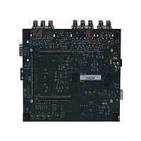
... EZ-KIT Lite board enables high speed, non- intrusive emulation. For evaluation of ADSP-BF531/ADSP-BF532/ADSP-BF533 processors, use the EZ-KIT Lite board available from Analog Devices. Order part number ADDS-BF533-EZLITE. The board comes with on-chip emulation capabilities and is equipped to enable software development. Multiple daughter cards are available. ...
Page 17
For details on target board design issues including mechanical layout, single processor connections, multiprocessor scan chains, signal buffering, signal termination, and emulator pod logic, see the Analog Devices JTAG Emulation Technical Refer ence (EE-68) on the Analog Devices website (www.analog.com)—use ...
Page 18
ADSP-BF531/ADSP-BF532/ADSP-BF533 PIN DESCRIPTIONS ADSP-BF531/ADSP-BF532/ADSP-BF533 processor pin defini tions are listed in Table 9. All pins are three-stated during and immediately after reset, except the memory interface, asynchronous memory control, and synchronous memory control pins, which are driven high. Table 9. ...
Page 19
Table 9. Pin Descriptions (Continued) Pin Name Type Function Port F: GPIO/Parallel Peripheral Interface Port/SPI/Timers PF0/SPISS I/O GPIO/SPI Slave Select Input PF1/SPISEL1/TACLK I/O GPIO/SPI Slave Select Enable 1/Timer Alternate Clock Input PF2/SPISEL2 I/O GPIO/SPI Slave Select Enable 2 PF3/SPISEL3/PPI_FS3 I/O ...
Page 20
ADSP-BF531/ADSP-BF532/ADSP-BF533 Table 9. Pin Descriptions (Continued) Pin Name Type Function RFS1 I/O SPORT1 Receive Frame Sync DR1PRI I SPORT1 Receive Data Primary DR1SEC I SPORT1 Receive Data Secondary TSCLK1 I/O SPORT1 Transmit Serial Clock TFS1 I/O SPORT1 Transmit Frame Sync ...
Page 21
SPECIFICATIONS Component specifications are subject to change without notice. OPERATING CONDITIONS Parameter Conditions 1 V Internal Supply Voltage Nonautomotive 400 MHz and 500 MHz speed grade models DDINT 1 V Internal Supply Voltage Nonautomotive 533 MHz speed grade models DDINT ...
Page 22
ADSP-BF531/ADSP-BF532/ADSP-BF533 ELECTRICAL CHARACTERISTICS Parameter V High Level Output Voltage OH V High Level Output Voltage OH V High Level Output Voltage OH V Low Level Output Voltage OL V Low Level Output Voltage High Level Input Current ...
Page 23
ABSOLUTE MAXIMUM RATINGS Stresses greater than those listed in the table may cause perma nent damage to the device. These are stress ratings only. Functional operation of the device at these or any other condi tions greater than those indicated ...
Page 24
ADSP-BF531/ADSP-BF532/ADSP-BF533 TIMING SPECIFICATIONS Table 12 through Table 15 describe the timing requirements for the ADSP-BF531/ADSP-BF532/ADSP-BF533 processor clocks. Take care in selecting MSEL, SSEL, and CSEL ratios so as not to exceed the maximum core clock and system clock as described ...
Page 25
Clock and Reset Timing Table 16 and Figure 11 describe clock and reset operations. Per Absolute Maximum Ratings on Page 23, combinations of CLKIN and clock multipliers/divisors must not result in core/ Table 16. Clock and Reset Timing Parameter Timing ...
Page 26
ADSP-BF531/ADSP-BF532/ADSP-BF533 Asynchronous Memory Read Cycle Timing Table 17. Asynchronous Memory Read Cycle Timing Parameter Timing Requirements t DATA15–0 Setup Before CLKOUT SDAT t DATA15–0 Hold After CLKOUT HDAT t ARDY Setup Before CLKOUT SARDY t ARDY Hold After CLKOUT HARDY ...
Page 27
Asynchronous Memory Write Cycle Timing Table 18. Asynchronous Memory Write Cycle Timing Parameter Timing Requirements t ARDY Setup Before CLKOUT SARDY t ARDY Hold After CLKOUT HARDY Switching Characteristics t DATA15–0 Disable After CLKOUT DDAT t DATA15–0 Enable After CLKOUT ...
Page 28
ADSP-BF531/ADSP-BF532/ADSP-BF533 SDRAM Interface Timing 1 Table 19. SDRAM Interface Timing Parameter Timing Requirements t DATA Setup Before CLKOUT SSDAT t DATA Hold After CLKOUT HSDAT Switching Characteristics 2 t CLKOUT Period SCLK t CLKOUT Width High SCLKH t CLKOUT Width ...
Page 29
External Port Bus Request and Grant Cycle Timing Table 20 and Figure 15 describe external port bus request and bus grant operations. Table 20. External Port Bus Request and Grant Cycle Timing Parameter Timing Requirements t BR Asserted to CLKOUT ...
Page 30
ADSP-BF531/ADSP-BF532/ADSP-BF533 Parallel Peripheral Interface Timing Table 21 and Figure 16 through Figure 21 on Page 33 parallel peripheral interface operations. Table 21. Parallel Peripheral Interface Timing Parameter Timing Requirements t PPI_CLK Width PCLKW 1 t PPI_CLK Period PCLK t External ...
Page 31
DATA0 IS SAMPLED PPI_CLK POLC = 0 PPI_CLK POLC = 1 POLS = 1 PPI_FS1 POLS = 0 POLS = 1 PPI_FS2 POLS = 0 t SDRPE PPI_DATA DATA SAMPLING/ FRAME SYNC SAMPLING EDGE PPI_CLK POLC = 0 PPI_CLK POLC ...
Page 32
ADSP-BF531/ADSP-BF532/ADSP-BF533 FRAME SYNC IS DRIVEN OUT PPI_CLK POLC = 0 PPI_CLK POLC = 1 t DFSPE t HOFSPE POLS = 1 PPI_FS1 POLS = 0 POLS = 1 PPI_FS2 POLS = 0 PPI_DATA PPI_CLK POLC = 0 PPI_CLK POLC = ...
Page 33
DATA DRIVING/ FRAME SYNC SAMPLING EDGE PPI_CLK POLC = 0 PPI_CLK POLC = 1 t SFSPE POLS = 1 PPI_FS1 POLS = 0 POLS = 1 PPI_FS2 POLS = 0 PPI_DATA Figure 21. PPI GP Tx Mode with External Frame ...
Page 34
ADSP-BF531/ADSP-BF532/ADSP-BF533 Serial Ports Table 22 through Table 25 on Page 35 and through Figure 23 on Page 36 describe Serial Port operations. Table 22. Serial Ports—External Clock Parameter Timing Requirements t TFSx/RFSx Setup Before TSCLKx/RSCLKx SFSE t TFSx/RFSx Hold After ...
Page 35
DATA RECEIVE—INTERNAL CLOCK DRIVE EDGE t SCLKIW RSCLKx t DFSI t t HOFSI SFSI RFSx t SDRI DRx NOTE: EITHER THE RISING EDGE OR FALLING EDGE OF RSCLKx OR TSCLKx CAN BE USED AS THE ACTIVE SAMPLING EDGE. DATA TRANSMIT—INTERNAL ...
Page 36
ADSP-BF531/ADSP-BF532/ADSP-BF533 EXTERNAL RFSx WITH MCE = 1, MFD = 0 RSCLKx RFSx DTx LATE EXTERNAL TFSx TSCLKx TFSx DTx DRIVE SAMPLE DRIVE t t SFSE/I HOFSE/I t DDTTE/I t DTENLFS t DTENE/I 1ST BIT t DDTLFSE DRIVE SAMPLE DRIVE t ...
Page 37
Serial Peripheral Interface (SPI) Port —Master Timing Table 26 and Figure 24 describe SPI port master operations. Table 26. Serial Peripheral Interface (SPI) Port—Master Timing Parameter Timing Requirements t Data Input Valid to SCK Edge (Data Input Setup) SSPIDM t ...
Page 38
ADSP-BF531/ADSP-BF532/ADSP-BF533 Serial Peripheral Interface (SPI) Port —Slave Timing Table 27 and Figure 25 describe SPI port slave operations. Table 27. Serial Peripheral Interface (SPI) Port—Slave Timing Parameter Timing Requirements t Serial Clock High Period SPICHS t Serial Clock Low Period ...
Page 39
Universal Asynchronous Receiver-Transmitter (UART) Port—Receive and Transmit Timing Figure 26 describes UART port receive and transmit operations. The maximum baud rate is SCLK/16. As shown in there is some latency between the generation internal UART interrupts and the external data ...
Page 40
ADSP-BF531/ADSP-BF532/ADSP-BF533 General-Purpose I/O Port F Pin Cycle Timing Table 28 and Figure 27 describe GPIO pin operations. Table 28. General-Purpose I/O Port F Pin Cycle Timing Parameter Timing Requirement t GPIO Input Pulse Width WFI Switching Characteristic t GPIO Output ...
Page 41
Timer Cycle Timing Table 29 and Figure 28 describe timer expired operations. The input signal is asynchronous in width capture mode and exter nal clock mode and has an absolute maximum input frequency MHz. SCLK Table 29. ...
Page 42
ADSP-BF531/ADSP-BF532/ADSP-BF533 JTAG Test and Emulation Port Timing Table 30 and Figure 29 describe JTAG port operations. Table 30. JTAG Port Timing Parameter Timing Requirements t TCK Period TCK t TDI, TMS Setup Before TCK High STAP t TDI, TMS Hold ...
Page 43
OUTPUT DRIVE CURRENTS Figure 30 through Figure 41 show typical current-voltage char acteristics for the output drivers of the ADSP-BF531/ ADSP-BF532/ADSP-BF533 processor. The curves represent the current drive capability of the output drivers as a function of output voltage. 150 ...
Page 44
ADSP-BF531/ADSP-BF532/ADSP-BF533 150 100 50 0 –50 –100 –150 0 0.5 1.0 1.5 2.0 SOURCE VOLTAGE (V) Figure 35. Drive Current B (V DDEXT –20 –40 –60 0 0.5 1.0 1.5 SOURCE VOLTAGE (V) Figure 36. Drive ...
Page 45
SOURCE VOLTAGE (V) Figure 41. Drive Current D (V DDEXT POWER DISSIPATION Many operating conditions can affect power dissipation. System designers should refer to Estimating Power for ADSP-BF531/ ...
Page 46
ADSP-BF531/ADSP-BF532/ADSP-BF533 plus the various output disable times as specified in the Specifications on Page 24 (for example t write cycle as shown in SDRAM Interface Timing on Page Capacitive Loading Output delays and holds are based on standard capacitive loads: ...
Page 47
RISE TIME 100 150 LOAD CAPACITANCE (pF) Figure 49. Typical Rise and Fall Times (10% to 90%) versus Load Capacitance for Driver 2.25 V DDEXT 10 9 ...
Page 48
ADSP-BF531/ADSP-BF532/ADSP-BF533 RISE TIME 100 150 LOAD CAPACITANCE (pF) Figure 55. Typical Rise and Fall Times (10% to 90%) versus Load Capacitance for Driver 2.25 ...
Page 49
BGA BALL ASSIGNMENT Table 34 lists the BGA ball assignment by signal. Page 50 lists the BGA ball assignment by ball number. Table 34. 160-Ball CSP_BGA Ball Assignment (Alphabetically by Signal) Signal Ball No. Signal ABE0 H13 DATA4 ABE1 ...
Page 50
ADSP-BF531/ADSP-BF532/ADSP-BF533 Table 35. 160-Ball CSP_BGA Ball Assignment (Numerically by Ball Number) Ball No. Signal Ball No. A1 VDDEXT C13 A2 PF8 C14 A3 PF9 D1 A4 PF10 D2 A5 PF11 D3 A6 PF14 D4 A7 PPI2 D5 A8 RTXO D6 ...
Page 51
Figure 57 lists the top view of the BGA ball configuration. Figure 58 lists the bottom view of the BGA ball configuration. ADSP-BF531/ADSP-BF532/ADSP-BF533 KEY ...
Page 52
ADSP-BF531/ADSP-BF532/ADSP-BF533 169-BALL PBGA BALL ASSIGNMENT Table 36 lists the PBGA ball assignment by signal. Page 53 lists the PBGA ball assignment by ball number. Table 36. 169-Ball PBGA Ball Assignment (Alphabetically by Signal) Signal Ball No. Signal ABE0 H16 DATA4 ...
Page 53
Table 37. 169-Ball PBGA Ball Assignment (Numerically by Ball Number) Ball No. Signal Ball No. A1 PF4 D16 A2 PF5 D17 A3 PF7 E1 A4 PF9 E2 A5 PF11 E16 A6 PF12 E17 A7 PF14 F1 A8 PPI3 F2 A9 ...
Page 54
ADSP-BF531/ADSP-BF532/ADSP-BF533 A1 BALL PAD CORNER BOTTOM VIEW ...
Page 55
LQFP PINOUT Table 38 lists the LQFP pinout by signal. lists the LQFP pinout by lead number. Table 38. 176-Lead LQFP Pin Assignment (Alphabetically by Signal) Signal Lead No. Signal ABE0 151 DATA3 ABE1 150 DATA4 ADDR1 149 DATA5 ...
Page 56
ADSP-BF531/ADSP-BF532/ADSP-BF533 Table 39. 176-Lead LQFP Pin Assignment (Numerically by Lead Number) Lead No. Signal Lead No. 1 GND 41 2 GND 42 3 GND 43 4 VROUT1 44 5 VROUT0 45 6 VDDEXT 46 7 GND 47 8 GND 48 ...
Page 57
OUTLINE DIMENSIONS Dimensions in the outline dimension figures are shown in millimeters. 0.27 0.22 0.17 SEATING PLANE 0.08 MAX LEAD COPLANARITY 0.15 0.05 NOTES 1. DIMENSIONS IN MILLIMETERS 2. ACTUAL POSITION OF EACH LEAD IS WITHIN 0.08 OF ITS IDEAL ...
Page 58
ADSP-BF531/ADSP-BF532/ADSP-BF533 A1 BALL PAD CORNER 19.00 BSC SQ TOP VIEW SIDE VIEW NOTES 1. DIMENSIONS ARE IN MILLIMETERS. 2. COMPLIES WITH JEDEC REGISTERED OUTLINE MS-034, VARIATION AAG-2 3. MINIMUM BALL HEIGHT 0.40 SURFACE MOUNT DESIGN Table 40 is provided as ...
Page 59
ORDERING GUIDE Temperature 1 Model Range ADSP-BF531SBB400 –40°C to +85°C ADSP-BF531SBBZ400 –40°C to +85°C ADSP-BF531SBBC400 –40°C to +85°C 2 ADSP-BF531SBBCZ400 –40°C to +85°C ADSP-BF531SBST400 –40°C to +85°C 2 ADSP-BF531SBSTZ400 –40°C to +85°C 2,3 ADSP-BF531WBBCZ-4A –40°C to +85°C 2,3 ADSP-BF531WBBZ-4A –40°C ...
Page 60
ADSP-BF531/ADSP-BF532/ADSP-BF533 Temperature 1 Model Range ADSP-BF533SBB500 –40°C to +85°C 2 ADSP-BF533SBBZ500 –40°C to +85°C ADSP-BF533SBBC500 –40°C to +85°C 2 ADSP-BF533SBBCZ500 –40°C to +85°C ADSP-BF533SBBC-5V –40°C to +85°C 2 ADSP-BF533SBBCZ-5V –40°C to +85°C 2 ADSP-BF533SBBCZ400 –40°C to +85°C ADSP-BF533SBST400 –40°C to ...