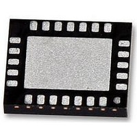
LMV7231SQE National Semiconductor, LMV7231SQE Datasheet - Page 15

LMV7231SQE
Manufacturer Part Number
LMV7231SQE
Description
IC, COMP, HEX, WINDOW, W/REF, 24LLP
Manufacturer
National Semiconductor
Datasheet
1.LMV7231SQENOPB.pdf
(18 pages)
Specifications of LMV7231SQE
Comparator Type
Low Power
No. Of Comparators
6
Response Time
7µs
Ic Output Type
Open Drain
Output Compatibility
NMOS
Supply Current
46µA
Supply Voltage Range
2.2V To 5.5V
Rohs Compliant
Yes
INPUT/OUTPUT VOLTAGE RANGE ABOVE V+
The LMV7231 Hex Window Comparator with 1.5% precision
can accurately monitor up to 6 power rails or batteries at one
time. The input and output voltages of the device can exceed
the supply voltage, V+, of the comparator, and can be up to
the absolute maximum ratings without causing damage or
performance degradation. The typical µC input pin with crow-
bar diode ESD protection circuitry will not allow the input to
go above V+, and thus its usefulness is limited in power sup-
ply supervision applications.
The supply independent inputs of the window comparator
blocks allow the LMV7231 to be tolerant of system faults. For
example if the power is suddenly removed from the LMV7231
due to a system malfunction yet there still exists a voltage on
the input, this will not be an issue as long as the monitored
input voltage does not exceed absolute maximum ratings.
Another example where this feature comes in handy is a bat-
tery sense application such as the one in
may be sitting on the shelf unbiased with V+ grounded, and
yet have a fully charged battery on board. If the comparator
measuring the battery had crowbar diodes, the diode from –
IN to V+ would turn on, sourcing current from the battery
eventually draining the battery. However, when using the
LMV7231 no current, except the low input bias current of the
device, will flow into the chip, and the battery charge will be
preserved.
The output pin voltages of the device can also exceed the
supply voltage, V+, of the comparator. This provides extra
flexibility and enables designs which pull up the outputs to
higher voltage levels to meet system requirements. For ex-
ample it’s possible to run the LMV7231 at its minimum oper-
ating voltage, V+ = +2.2V, but pull up the output up to the
absolute maximum ratings to bias a blue LED, with a forward
voltage of V
In a power supply supervision application the hardwired
LMV7231 is a sound solution compared to the uC with soft-
ware alternative for several reasons. First, startup is faster.
During startup you don’t need to account for code loading
time, oscillator ramp time, and reset time. Second, operation
is quick. The LMV7231 has a maximum propagation delay in
the µs and isn’t affected by sampling and conversion delays
related to reading data, calculating data, and setting flags.
Third, less overhead. The LMV7231 doesn’t require an ex-
pensive power consuming microcontroller nor is it dependent
on controller code which could get damaged or crash.
FIGURE 6. Battery Sense Application
F
= +4V.
Figure
30114958
6. The boards
15
POWER SUPPLY BYPASSING
Bypass the supply pin, V+, with a 0.1 μF ceramic capacitor
placed close to the V+ pin. If transients with rise/fall times of
100’s μs and magnitudes of 100’s mV are expected on the
power supply line a RC low pass filter network as shown in
Figure 7
bypass network is used power supply transients can cause
the internal voltage reference of the comparator to temporarily
shift potentially resulting in a brief incorrect comparator out-
put. For example if an RC network with 100Ω resistance and
10μF capacitance (1.1ms rise time) is used the voltage ref-
erence will shift temporarily the amount, V
Sensitivity (V
tics table.
POWER SUPPLY SUPERVISION
Figure 8
LMV7231. This application uses the efficient, easy to use
LM25007 step-down switching regulator. This switching reg-
ulator can handle a 9V – 42V input voltage range and it’s
regulated output voltage is set to 5V with R2 = R3 = 3kΩ.
Resistor R6 and capacitors C6, C7 are utilized to minimize
output ripple voltage per the LM25007 evaluation board ap-
plication note.
The comparator voltage window is set to 5V +/- 5% by
R7=1.15kΩ , R8=10Ω, R9=95.3Ω. See
AGE DIVIDER SELECTION
mation section of the datasheet for details on how to set the
comparator voltage window.
With components selected the output ripple voltage seen on
the LM25007 is approximately 30 - 35mV and is reduced to
about 4mV at the comparator input, +IN1, by the resistor di-
vider. This ripple voltage can be reduced multiple ways. First,
user can operate the device in continuous conduction mode
rather than discontinuous conduction mode. To do this in-
crease the load current of the device (see LM25007 datasheet
for more details). However, make sure not to exceed the pow-
er rating of the resistors in the resistor ladder. Second, ripple
can be reduced further with a bypass cap, C9, at the resistor
divider. If desired a user can select a 1uF capacitor to achieve
less than 3mV ripple at +IN1. However, there is a tradeoff and
adding capacitance at this node will lower the system re-
sponse time.
shows a power supply supervision circuit utilizing the
is recommended for additional bypassing. If no such
FIGURE 7. Power Supply Bypassing
TH
PSS), specified in the Electrical Characteris-
section in the Application Infor-
3 RESISTOR VOLT-
TH
30114959
Power Supply
www.national.com


