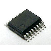
Si8442BA-D-IU Silicon Laboratories Inc, Si8442BA-D-IU Datasheet - Page 21

Si8442BA-D-IU
Manufacturer Part Number
Si8442BA-D-IU
Description
Isolator Interface IC Quad Ch 1 kV Iso 150M 2/2
Manufacturer
Silicon Laboratories Inc
Specifications of Si8442BA-D-IU
Number Of Channels
4
Propagation Delay Time
35 ns
Supply Voltage (max)
5.5 V
Supply Voltage (min)
2.7 V
Supply Current
9 mA
Power Dissipation
275 mW
Maximum Operating Temperature
+ 125 C
Mounting Style
SMD/SMT
Package / Case
QSOP-16
Minimum Operating Temperature
- 40 C
Lead Free Status / Rohs Status
Details
Notes:
1. Enable inputs EN1 and EN2 can be used for multiplexing, for clock sync, or other output control. EN1, EN2 logic
2. X = not applicable; H = Logic High; L = Logic Low.
3. When using the enable pin (EN) function, the output pin state is driven to a logic low state when the EN pin is disabled
Si8440
Si8441
Si8442
Si8445
P/N
operation is summarized for each isolator product in Table 13. These inputs are internally pulled-up to local VDD by a
3 µA current source allowing them to be connected to an external logic level (high or low) or left floating. To minimize
noise coupling, do not connect circuit traces to EN1 or EN2 if they are left floating. If EN1, EN2 are unused, it is
recommended they be connected to an external logic level, especially if the Si84xx is operating in a noisy environment.
(EN = 0) in Revision C. Revision D outputs go into a high-impedance state when the EN pin is disabled (EN = 0). See
"3. Errata and Design Migration Guidelines" on page 25 for more details.
EN1
—
—
—
H
X
X
H
X
X
L
L
1,2
EN2
—
H
X
X
H
X
X
H
L
L
L
1,2
Outputs B1, B2, B3, B4 are enabled and follow the input state.
Outputs B1, B2, B3, B4 are disabled and Logic Low or in high impedance state.
Output A4 enabled and follows the input state.
Output A4 disabled and Logic Low or in high impedance state.
Outputs B1, B2, B3 are enabled and follow the input state.
Outputs B1, B2, B3 are disabled and Logic Low or in high impedance state.
Outputs A3 and A4 are enabled and follow the input state.
Outputs A3 and A4 are disabled and Logic Low or in high impedance state.
Outputs B1 and B2 are enabled and follow the input state.
Outputs B1 and B2 are disabled and Logic Low or in high impedance state.
Outputs B1, B2, B3, B4 are enabled and follow the input state.
Table 13. Enable Input Truth Table
Rev. 1.4
Operation
1
Si8440/41/42/45
3
3
3
3
21
3


