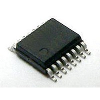
Si8442BA-D-IU Silicon Laboratories Inc, Si8442BA-D-IU Datasheet - Page 21

Si8442BA-D-IU
Manufacturer Part Number
Si8442BA-D-IU
Description
Isolator Interface IC Quad Ch 1 kV Iso 150M 2/2
Manufacturer
Silicon Laboratories Inc
Specifications of Si8442BA-D-IU
Number Of Channels
4
Propagation Delay Time
35 ns
Supply Voltage (max)
5.5 V
Supply Voltage (min)
2.7 V
Supply Current
9 mA
Power Dissipation
275 mW
Maximum Operating Temperature
+ 125 C
Mounting Style
SMD/SMT
Package / Case
QSOP-16
Minimum Operating Temperature
- 40 C
Lead Free Status / Rohs Status
Details
3.3.3. RF Radiated Emissions
The Si84xx family uses a RF carrier frequency of approximately 700 MHz. This results in a small amount of
radiated emissions at this frequency and its harmonics. The radiation is not from the IC chip but due to a small
amount of RF energy driving the isolated ground planes which can act as a dipole antenna.
The unshielded Si84xx evaluation board passes FCC Class B (Part 15) requirements. Table 14 shows measured
emissions compared to FCC requirements. Note that the data reflects worst-case conditions where all inputs are
tied to logic 1 and the RF transmitters are fully active.
Radiated emissions can be reduced if the circuit board is enclosed in a shielded enclosure or if the PCB is a less
efficient antenna.
3.3.4. RF, Magnetic, and Common Mode Transient Immunity
The Si84xx families have very high common mode transient immunity while transmitting data. This is typically
measured by applying a square pulse with very fast rise/fall times between the isolated grounds. Measurements
show no failures at 25 kV/µs (typical). During a high surge event, the output may glitch low for up to 20–30 ns, but
the output corrects immediately after the surge event.
The Si84xx families pass the industrial requirements of CISPR24 for RF immunity of 10 V/m using an unshielded
evaluation board. As shown in Figure 14, the isolated ground planes form a parasitic dipole antenna. The PCB
should be laid-out to not act as an efficient antenna for the RF frequency of interest. RF susceptibility is also
significantly reduced when the end system is housed in a metal enclosure, or otherwise shielded.
The Si84xx digital isolator can be used in close proximity to large motors and various other magnetic-field
producing equipment. In theory, data transmission errors can occur if the magnetic field is too large and the field is
too close to the isolator. However, in actual use, the Si84xx devices provide extremely high immunity to external
magnetic fields and have been independently evaluated to withstand magnetic fields of at least 1000 A/m
according to the IEC 61000-4-8 and IEC 61000-4-9 specifications.
Frequency
(MHz)
1424
2136
2848
4272
4984
5696
712
Table 14. Radiated Emissions
Figure 14. Dipole Antenna
GND1
Measured
(dBµV/m)
29
39
42
43
44
44
44
Antenna
Rev. 0.1
Dipole
Isolator
FCC Spec
(dBµV/m)
37
54
54
54
54
54
54
GND2
Compared to
Spec (dB)
–15
–12
–10
–10
–10
–11
–8
Si84x/5x QSOP
21


