PIC-P18-20-MHZ Olimex Ltd., PIC-P18-20-MHZ Datasheet - Page 6
PIC-P18-20-MHZ
Manufacturer Part Number
PIC-P18-20-MHZ
Description
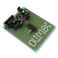
DEVELOPMENT BOARD FOR 18 PIN PIC MICROCONTROLLERS
Manufacturer
Olimex Ltd.
Datasheet
1.PIC-P18-20MHZ.pdf
(8 pages)
Specifications of PIC-P18-20-MHZ
External Height
80mm
External Width
100mm
Mcu Supported Families
PIC-P18
Rohs Compliant
Yes


SOFTWARE:
DEMO1:
DEMO2:
DEMO3:
This is demo code which blinks the LED on PIC-P18 board.
Note:
This is demo code which show how to read BUTTON status and to switch
the LED ON when button is pressed and LED off when the button is
depressed.
This is demo code, which show how to use the USART to send and receive
characters from host PC via RS232 cable.
The MAX232 by default is not connected to PIC on the board so you have to
solder two wires – one from RB2 (pin #8) of PIC16F628 Tx signal to MAX232
Rx labeled pin, and second from RB1 (pin #7) of PIC16F628 Rx signal to
MAX232 Tx labeled pin.
IMPORTANT: as seen from the schematic RB2 is also connected to the
User button, this means if you press the button during the
communication the communication will be lost and you may burn your
PIC UART port!
You must program the HEX code to PIC16F628 and run the code.
If you programmed the PIC correctly and wired the UART, when you open
Hyperterminal on your host PC computer with 9600 bps, 8 data bit, 1 stop
bit, No flow control and apply power supply to the PIC-P18 every character
you type on the hyperterminal will be printed back with “*” i.e. if you type
“abc” you will receive “a*b*c*”.
PIC16F628-I/P
PIC16F628-I/P
PIC16F628-I/P
LED jumper should be closed!
BLINK LED
BUTTON read
RS232 send / receive routines
Page 6
Related parts for PIC-P18-20-MHZ
Image
Part Number
Description
Manufacturer
Datasheet
Request
R

Part Number:
Description:
MCU, MPU & DSP Development Tools PROTOTYPE BRD FOR 18 PIN PIC
Manufacturer:
Olimex Ltd.
Datasheet:


Part Number:
Description:
UC/OS-II For Microchip PIC24xx - Platform License
Manufacturer:
MICRIUM
Part Number:
Description:
UC/OS-II For Microchip PIC24xx - Product Line License
Manufacturer:
MICRIUM
Part Number:
Description:
UC/OS-II For Microchip PIC24xx - Single Product License
Manufacturer:
MICRIUM
Part Number:
Description:
UC/OS-III For Microchip PIC24xx - Platform License
Manufacturer:
MICRIUM
Part Number:
Description:
UC/OS-III For Microchip PIC24xx - Product Line License
Manufacturer:
MICRIUM
Part Number:
Description:
UC/OS-III For Microchip PIC24xx - Single Product License
Manufacturer:
MICRIUM

Part Number:
Description:
MCU, MPU & DSP Development Tools ETHERNET CONTROLLER HEADER BRD 50x40mm
Manufacturer:
Olimex Ltd.
Datasheet:

Part Number:
Description:
Microcontroller & Microprocessor Development Tools TCP-IP DEV BRD PIC32MX460F512
Manufacturer:
Olimex Ltd.
Datasheet:

Part Number:
Description:
Microcontroller & Microprocessor Development Tools PROTOTYPE BOARD TMS320F28027
Manufacturer:
Olimex Ltd.
Datasheet:

Part Number:
Description:
Microcontroller & Microprocessor Development Tools HDR BRD FOR LPC3131
Manufacturer:
Olimex Ltd.
Datasheet:

Part Number:
Description:
Microcontroller & Microprocessor Development Tools MP3 PLYR MOD WITH VS1002
Manufacturer:
Olimex Ltd.
Datasheet:
Part Number:
Description:
Microcontroller & Microprocessor Development Tools MP3 PLYR MOD BAT WITH VS1002
Manufacturer:
Olimex Ltd.
Datasheet: