B43693A2226Q009 EPCOS Inc, B43693A2226Q009 Datasheet - Page 10
B43693A2226Q009
Manufacturer Part Number
B43693A2226Q009
Description
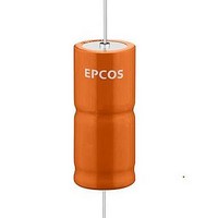
Aluminum Electrolytic Capacitors - Leaded 22UF 250V AL-ELKO AXIAL LEADED
Manufacturer
EPCOS Inc
Series
B43693r
Datasheet
1.B43793A2226Q000.pdf
(14 pages)
Specifications of B43693A2226Q009
Capacitance
22 uF
Tolerance
- 10 %, 30 %
Voltage Rating
250 Volts
Esr
2300 mOhms
Operating Temperature Range
- 40 C to + 125 C
Termination Style
Axial
Dimensions
14 mm Dia. x 30 mm L
Product
General Purpose Electrolytic Capacitors
Load Life
2500 Hrs
Ripple Current
3.32 Amps
Lead Free Status / Rohs Status
No
Available stocks
Company
Part Number
Manufacturer
Quantity
Price
Company:

Part Number:
B43693A2226Q009
Manufacturer:
EPCOS
Quantity:
20 000
Company:
Part Number:
B43693A2226Q009
Manufacturer:
MITSUBISHI
Quantity:
2 400


Product safety
The table below summarize the safety instructions that must be observed without fail. A detailed
description can be found in the relevant sections of chapter "General technical information".
Topic
Polarity
Reverse voltage
Upper category
temperature
Maintenance
Mounting
position of screw
terminal capacitors
Mounting of
single-ended
capacitors
Robustness of
terminals
Soldering
Please read Cautions and warnings and
Important notes at the end of this document.
B43693, B43793
High voltage
Safety information
Make sure that polar capacitors are connected
with the right polarity.
Voltages polarity classes should be prevented by
connecting a diode.
Do not exceed the upper category temperatur.
Make periodic inspections of the capacitors.
Before the inspection, make sure that the power
supply is turned off and carefully discharge the
electricity of the capacitors.
Do not apply any mechanical stress to the
capacitor terminals.
Do not mount the capacitor with the terminals
(safety vent) upside down.
The internal structure of single-ended capacitors
might be damaged if excessive force is applied to
the lead wires.
Avoid any compressive, tensile or flexural stress.
Do not move the capacitor after soldering to PC
board.
Do not pick up the PC board by the soldered
capacitor.
Do not insert the capacitor on the PC board with a
hole space different to the lead space specified.
The following maximum tightening torques must
not be exceeded when connecting screw
terminals:
M5: 2 Nm
M6: 2.5 Nm
Do not exceed the specified time or temperature
limits during soldering.
125 C
Page 10 of 14
Reference
Chapter "General
technical information"
1
"Basic construction of
aluminum electrolytic
capacitors"
3.1.6
"Reverse voltage"
7.2
"Maximum permissible
operating temperature"
10
"Maintenance"
11.1
"Mounting positions of
capacitors with screw
terminals"
11.4
"Mounting
considerations for
single-ended capacitors"
11.3
"Mounting torques"
11.5
"Soldering"
Related parts for B43693A2226Q009
Image
Part Number
Description
Manufacturer
Datasheet
Request
R

Part Number:
Description:
Axial-lead and Soldering Star Capacitors
Manufacturer:
EPCOS [EPCOS]
Datasheet:


Part Number:
Description:
CAP .15UF 63V METAL POLY
Manufacturer:
EPCOS Inc
Datasheet:


Part Number:
Description:
CAP .01UF 400V METAL POLY
Manufacturer:
EPCOS Inc
Datasheet:
