LTC1059CN#PBF Linear Technology, LTC1059CN#PBF Datasheet
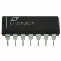
IC FILTER BUILDING BLOCK 14-DIP

LTC1059CN#PBF

Manufacturer Part Number
LTC1059CN#PBF
Description
IC FILTER BUILDING BLOCK 14-DIP
Manufacturer
Linear Technology
Datasheet

Specifications of LTC1059CN#PBF

Filter Type
Universal Switched Capacitor
Frequency - Cutoff Or Center
40kHz
Number Of Filters
1
Max-order
2nd
Voltage - Supply
±2.37 V ~ 5 V
Mounting Type
Through Hole
Package / Case
14-DIP (0.300", 7.62mm)
Lead Free Status / RoHS Status
Lead free / RoHS Compliant

Available stocks

Company
Part Number
Manufacturer
Quantity
Price
Company:
Part Number:
LTC1059CN#PBF
Manufacturer:
LT
Quantity:
175
FEATURES
APPLICATIO S
TYPICAL APPLICATIO
LTCMOS trademark of Linear Technology Corporation.
, LTC and LT are registered trademarks of Linear Technology Corporation.
All Filter Parameters Guaranteed Over Temperature
Wide Center Frequency Range (0.1Hz to 40kHz)
Low Noise, Wide Dynamic Range
Guaranteed Operation for ±2.37V and ±5V Supply
Low Power Consumption
Guaranteed Clock-to-Center Frequency Accuracy of
0.8%
Guaranteed Low Offset Voltages Over Temperature
Very Low Center Frequency and Q Tempco
Clock Input T
Separate Highpass (or Notch or Allpass), Bandpass,
Lowpass Outputs
Sinewave Oscillators
Sweepable Bandpass/Notch Filters
Full Audio Frequency Filters
Tracking Filters
Wide Range 2nd Order Bandpass/Notch Filter with Q = 10
T
2
DC-200kHz
L CLOCK IN ≤ 2MHz
V
IN
50k
2
L or CMOS Compatible
U
8V
7.15k
50k
1
2
3
4
5
6
7
BP
N/AP/HP
INV1
S1
S
V
LSh
NOTCH OUT
BP OUT
A
+
50/100/HOLD
LTC1059
U
AGND
INV2
CLK
V
LP
V
02
14
13
12
11
10
9
8
Switched Capacitor Universal Filter
–8V
1059 TA01a
DESCRIPTIO
The LTC
mance, active filter building block and an uncommitted op
amp. The filter building block together with an external
clock and 2 to 5 resistors can produce various 2nd order
functions which are available at its three output pins. Two
out of three always provide lowpass and bandpass func-
tions while the third output pin can produce notch or
highpass or allpass. The center frequency of these func-
tions can be tuned from 0.1Hz to 40kHz and is dependent
on an external clock or an external clock and a resistor
ratio. The filter can handle input frequencies up to 100kHz.
The uncommitted op amp can be used to obtain additional
allpass and notch functions, for gain adjustment or for
cascading techniques.
Higher than 2nd order filter functions can be obtained by
cascading the LTC1059 with the LTC1060 dual universal
filter or the LTC1061 triple universal filter. Any classical
filter realization (such as Butterworth, Cauer, Bessel and
Chebyshev) can be formed.
The LTC1059 can be operated with single or dual supplies
ranging from ±2.37V to ±8V (or 4.74V to 16V single
supply).
The LTC1059 is manufactured by using Linear Technology’s
enhanced LTCMOS
®
1059 consists of a general purpose, high perfor-
1.2
1.0
0.8
0.6
0.4
0.2
0
Center Frequency and Q Error
0
High Performance
CENTER FREQUENCY
T
A
5
= 25°C
TM
U
IDEAL CENTER FREQUENCY (kHz)
CLOCK
10
silicon gate process.
15
20
FREQUENCY
=
CENTER
25
ERROR
Q ERROR
35.35
1
30
35
1058 TA01b
40
LTC1059
45
30
25
20
15
10
5
0
1059fd
1

Related parts for LTC1059CN#PBF

LTC1059CN#PBF Summary of contents

Page 1

... Separate Highpass (or Notch or Allpass), Bandpass, Lowpass Outputs U APPLICATIO S Sinewave Oscillators Sweepable Bandpass/Notch Filters Full Audio Frequency Filters Tracking Filters , LTC and LT are registered trademarks of Linear Technology Corporation. LTCMOS trademark of Linear Technology Corporation. U TYPICAL APPLICATIO Wide Range 2nd Order Bandpass/Notch Filter with NOTCH OUT 50k BP OUT ...

Page 2

LTC1059 ABSOLUTE AXI U RATI GS (Note 1) Supply Voltage ........................................................ 18V Power Dissipation .............................................. 500mW Operating Temperature Range LTC1059C ................................... –40°C ≤ T LTC1059AM, LTC1059M ........... –55°C ≤ T Storage Temperature Range ................. – 65°C to ...

Page 3

ELECTRICAL CHARACTERISTICS temperature range, otherwise specifications are (Complete Filter ±5V Clock Input Level unless otherwise specified. S PARAMETER DC Lowpass Gain Accuracy BP Gain Accuracy Clock Feedthrough Max Clock Frequency ...

Page 4

LTC1059 W U TYPICAL PERFOR A CE CHARACTERISTICS Graph 1. Mode Deviation vs Q CLK 0 0 ± 25° 250kHz CLK 0 –0.4 –0.8 f CLK –1.2 ...

Page 5

W U TYPICAL PERFOR A CE CHARACTERISTICS Graph 10. Mode CLK and Q CLK 1 ±2. 25° 0.8 CLK = 100 0.6 0.4 0.2 ...

Page 6

LTC1059 W U TYPICAL PERFOR A CE CHARACTERISTICS Graph 19. Mode 3 ( and Q CLK 0 CLK 0 ± 25° 0.6 CLK = 100:1 f ...

Page 7

... NOTE: LEAD DIMENSIONS APPLY TO SOLDER DIP/PLATE OR TIN PLATE LEADS Information furnished by Linear Technology Corporation is believed to be accurate and reliable. However, no responsibility is assumed for its use. Linear Technology Corporation makes no represen- tation that the interconnection of its circuits as described herein will not infringe on existing patent rights. – ...

Page 8

... N14 1002 .337 – .344 NOTE .150 – .157 (3.810 – 3.988) NOTE 3 N .004 – .010 (0.101 – 0.254) .050 (1.270) BSC S14 0502 LW/TP 0103 1K REV D • PRINTED IN USA  LINEAR TECHNOLOGY CORPORATION 2001 1059fd ...

Related keywords