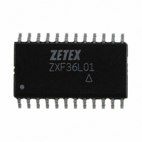
ZXF36L01W24 Diodes Zetex, ZXF36L01W24 Datasheet - Page 8

ZXF36L01W24
Manufacturer Part Number
ZXF36L01W24
Description
IC FILTER VARIABLE Q WIDE 24SOIC
Manufacturer
Diodes Zetex
Datasheet
1.ZXF36L01W24.pdf
(12 pages)
Specifications of ZXF36L01W24
Filter Type
Variable Q Bandpass
Frequency - Cutoff Or Center
150kHz
Number Of Filters
1
Voltage - Supply
5.0V
Mounting Type
Surface Mount
Package / Case
24-SOIC (7.5mm Width)
Lead Free Status / RoHS Status
Contains lead / RoHS non-compliant
Max-order
-
Available stocks
Company
Part Number
Manufacturer
Quantity
Price
Company:
Part Number:
ZXF36L01W24
Manufacturer:
ADI
Quantity:
1 534
Q
DESIGNING FOR A VALUE OF Q
As mentioned on the configuration pages, there is a
proportional, but non-linear relationship between the
ratio of Rf and Ri, and Q.
These resistors define the gain of an inverting amplifier
that determines the peak value gain and therefore the Q
of the filter,Q is defined as:
This value of required gain is critical. As the maximum
value of Q is approached, too much gain will cause the
filter to oscillate at the centre frequency, fo. A small
reduction of gain will cause the value of Q to fall
significantly. Therefore, for high values of Q or tight
tolerances of lower values of Q, the resistor ratio must
be trimmed as shown.
Frequency dependant effects must be accounted for in
determining the appropriate gain. As the frequency
increases because of internal phase shift effects the
effective circuit gain reduces and thus Q Factor reduces.
The frequency effect is not a problem for circuits where
the fo remains constant, as the phase shifts are
accounted for permanently. For designs where Q is high
and fo is to be ‘swept’, care must be taken that a gain
appropriate at the highest frequency does not cause
oscillation at the lowest.
This diagram shows the exponential relationship between gain and Q Factor. (fo = 140 kHz)
ZXF36L01
3
dB Bandwidth
f
O
8
Below are some typical values of gain required for
several example conditions:
Example1
fo = 48kHz,
Example2
fo = 140kHz,
It can be seen from these examples that the higher Q
example actually has a lower inverting amplifier gain.
As mentioned before, the frequency will affect the
value of gain. The Q Factor v Frequency graph
illustrates this effect.
These examples show that the gain required is
nominally 2. For the specified range of Q: 0.5 to 50
(values up to 250 are obtainable), the gain values vary
from 1.9 to 2.5 correspondingly.
Due to internal gain errors, when the absolute value
of Q is increased, the device to device variation in Q
will also increase.
Suggestion for gain setting component values.
Pin 9
Q=60,
Q=15,
10k
R = 10k , C = 320pF
Rf/Ri = 36.6k / 18 k
R = 10k , C = 100pF
Rf/Ri = 37k / 18k => 2.055
Pin 10
2k
ISSUE 3 - JANUARY 2002
22k
Pin 11
=> 2.033


