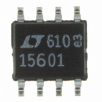
LTC1560-1CS8#PBF Linear Technology, LTC1560-1CS8#PBF Datasheet - Page 5

LTC1560-1CS8#PBF
Manufacturer Part Number
LTC1560-1CS8#PBF
Description
IC FILTER ELLIPTIC LOWPASS 8SOIC
Manufacturer
Linear Technology
Datasheet
1.LTC1560-1CS8PBF.pdf
(8 pages)
Specifications of LTC1560-1CS8#PBF
Filter Type
Continuous Lowpass
Frequency - Cutoff Or Center
1MHz
Number Of Filters
1
Max-order
5th
Voltage - Supply
±4.5 V ~ 5.5 V
Mounting Type
Surface Mount
Package / Case
8-SOIC (3.9mm Width)
Number Of Circuits
Single
Order Filter (max)
5th
Single Supply Voltage (typ)
Not RequiredV
Dual Supply Voltage (typ)
±5V
Power Supply Requirement
Dual
Single Supply Voltage (min)
Not RequiredV
Single Supply Voltage (max)
Not RequiredV
Operating Temperature (min)
0C
Operating Temperature (max)
70C
Operating Temperature Classification
Commercial
Lead Free Status / RoHS Status
Lead free / RoHS Compliant
Available stocks
Company
Part Number
Manufacturer
Quantity
Price
PIN
GND (Pins 1, 3): Analog Ground Pins. The quality of the
analog ground can affect the filter performance. For dual
supply operation the analog ground pin should be con-
nected to an analog ground plane surrounding the pack-
age. The analog ground plane should be connected to a
digital ground plane (if any) at a single point. For single
supply operation, the analog ground pin should be biased
at one-half the power supply across the device (see
Figure 1) and the analog ground plane should then be
connected to V
V
inverting input of a high frequency op amp through an 8k
resistor.
V
positive power supply (Pins 4 and 6 respectively) should
be decoupled with a 0.1 F capacitor in parallel with a
0.01 F. Both capacitors should be types designed for
decoupling video frequencies and they should be placed
as close as possible to the power supply pins of the filter.
Parallel routing of high frequency signal paths should be
avoided; they will couple into the device’s power supply
pins and cause gain inaccuracy and stopband degrada-
IN
–
, V
U
(Pin 2): The filter input is internally connected to the
+
FUNCTIONS
(Pins 4, 6): Power Supply Pins. The negative and
U
–
(Pin 4).
U
SYSTEM GROUND
1 F
Figure 1. Connections for Single Supply Operation
0.01 F
V
+
10k
ANALOG GROUND PLANE
10k
0.1 F
V
tion. The power supplies can be applied in any order, that
is, the positive supply can be applied before the negative
supply and vice versa. Switching power supplies are not
recommended.
0.5f
frequency is internally programmed for 500kHz. By tying
Pin 5 low the cutoff frequency will switch to 1MHz. Pin 5
should not be left floating. The logic threshold of Pin 5 is
approximately 0.4 times the total power supply across the
device.
SHDN (Pin 7): Shutdown. Under normal operating condi-
tions, Pin 7 should be shorted either to the analog ground
(Pin 1) or to V
operation will stop and the IC will be placed in a power
saving mode. The power supply current will then be
reduced to 1mA. For a 5V supply, the logic threshold of
Pin 7 is 2.5V. Pin 7 is internally connected to the analog
ground pin via a 50k resistor.
V
The total harmonic distortion of the filter will degrade
when driving coaxial cables or loads less than 10k without
an output buffer.
IN
OUT
0.01 F
C
1
2
3
4
/f
(Pin 8): The filter output pin can sink or source 1mA.
GND
V
GND
V
C
IN
–
LTC1560-1
(Pin 5): By tying Pin 5 high the filter cutoff
0.5f
SHDN
DIGITAL GROUND
V
–
C
OUT
V
/f
(Pin 4). If Pin 7 is pulled high to V
+
C
PLANE
8
7
6
5
1560-1 F01
V
GND OR V
OUT
+
LTC1560-1
sn15601 15601fs
+
, the filter
5


