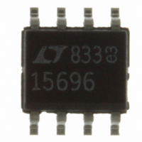
LTC1569CS8-6#PBF Linear Technology, LTC1569CS8-6#PBF Datasheet - Page 9

LTC1569CS8-6#PBF
Manufacturer Part Number
LTC1569CS8-6#PBF
Description
IC FILTER 10TH ORDR LOWPASS8SOIC
Manufacturer
Linear Technology
Datasheet
1.LTC1569CS8-6PBF.pdf
(12 pages)
Specifications of LTC1569CS8-6#PBF
Filter Type
Linear Phase, Lowpass Switched Capacitor
Frequency - Cutoff Or Center
300kHz
Number Of Filters
1
Max-order
10th
Mounting Type
Surface Mount
Package / Case
8-SOIC (3.9mm Width)
Lead Free Status / RoHS Status
Lead free / RoHS Compliant
Voltage - Supply
-
Available stocks
Company
Part Number
Manufacturer
Quantity
Price
APPLICATIONS
f
typical variation in dynamic input impedance for a given
clock frequency is 10%.
Wideband Noise
The wideband noise of the filter is the RMS value of the
device’s output noise spectral density. The wideband
noise data is used to determine the operating signal-to-
noise at a given distortion level. The wideband noise is
nearly independent of the value of the clock frequency and
excludes the clock feedthrough. Most of the wideband
noise is concentrated in the filter passband and cannot be
removed with post filtering (Table 2). Table 3 lists the
typical wideband noise for each supply.
Table 2. Wideband Noise vs Supply Voltage, Single 3V Supply
Bandwidth
DC to f
DC to 2 • f
DC to f
Table 3. Wideband Noise vs Supply Voltage, f
Power Supply
3V
5V
Clock Feedthrough
Clock feedthrough is defined as the RMS value of the clock
frequency and its harmonics that are present at the filter’s
OUT pin (Pin 8). The clock feedthrough is measured with
IN
PC board layout and the power supply decoupling. Table 4
shows the clock feedthrough (the RMS sum of the first 11
harmonics) when the LTC1569-6 is self-clocked with
R
clock feedthrough can be reduced with a simple RC post
filter.
Table 4. Clock Feedthrough
Power Supply
3V
5V
CUTOFF
5V
5V
EXT
+
and IN
= 10k, DIV/CLK (Pin 5) open (divide-by-4 mode). The
CUTOFF
CLK
), as shown in the Typical Applications section. The
CUTOFF
–
(Pins 1 and 2) grounded and depends on the
U
INFORMATION
U
Total Integrated Noise
Total Integrated Noise
W
DC to 2 • f
Feedthrough
110 V
100 V
105 V
0.1mV
0.3mV
0.9mV
80 V
95 V
95 V
CUTOFF
RMS
RMS
RMS
RMS
RMS
RMS
RMS
RMS
RMS
CUTOFF
= 64kHz
U
DC Accuracy
DC accuracy is defined as the error in the output voltage
after DC offset and DC gain errors are removed. This is
similar to the definition of the integral nonlinearity in A/D
converters. For example, after measuring values of V
vs V
shows that V
straight line that best fits the data. The DC accuracy
describes how much the actual data deviates from this
straight line (i.e., DCERROR = V
+ 0.00134V). In a 12-bit system with a full-scale value of
2V, the LSB is 488 V. Therefore, if the DCERROR of the
filter is less than 488 V over a 2V range, the filter has
12-bit DC accuracy. Figure 9 illustrates the typical DC
accuracy of the LTC1569-6 on a single 5V supply.
DC Offset
The output DC offset of the LTC1569-6 is trimmed to less
than 5mV. The trimming is performed with V
–1.1V with the filter cutoff frequency set to 4kHz (R
10k, DIV/CLK shorted to V
performance, appropriate PC layout techniques should be
used. The filter IC should be soldered to the PC board. The
power supplies should be well decoupled including a 1 F
ceramic capacitor from V
plane should be used. Noisy signals should be isolated
from the filter input pins.
When the power supply is 3V, the output DC offset should
change less than 2mV when the clock frequency varies
from 64kHz to 4096kHz. When the clock frequency is
fixed, the output DC offset will typically change by less
than 3mV ( 15mV) when the power supply varies from
3V to 5V ( 5V) in the divide-by-1 mode. In the divide-by-
4 or divide-by-16 modes, the output DC offset will typically
change less than – 9mV (– 27mV) when the power supply
varies from 3V to 5V ( 5V). The offset is measured with
respect to GND (Pin 3).
Aliasing
Aliasing is an inherent phenomenon of sampled data
filters. In lowpass filters significant aliasing only occurs
when the frequency of the input signal approaches the
sampling frequency or multiples of the sampling fre-
IN(DC)
for a typical LTC1569-6, a linear regression
OUT(DC)
= V
IN(DC)
+
+
). To obtain optimum DC offset
(Pin 7) to V
• 0.99854 + 0.00134V is the
OUT(DC)
LTC1569-6
– (V
–
(Pin 4). A ground
IN(DC)
• 0.99854
S
= 1.9V,
OUT(DC)
EXT
9
=


