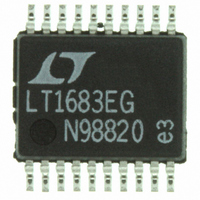
LTC1562CG-2#PBF Linear Technology, LTC1562CG-2#PBF Datasheet

LTC1562CG-2#PBF
Specifications of LTC1562CG-2#PBF
Available stocks
Related parts for LTC1562CG-2#PBF
LTC1562CG-2#PBF Summary of contents
Page 1
... LTC1562-2. Varying the gain of a section can achieve a dynamic range as high as 114dB with a 5V supply. Other cutoff frequency ranges can be provided upon request. Please contact LTC Marketing. , LTC and LT are registered trademarks of Linear Technology Corporation. 7.87k V OUT1 20 ...
Page 2
... C = 30pF 2.375V, V2 Output Has 2.375V 400kHz, Input AC GND 5V 400kHz, Input AC GND 400kHz 200kHz Input AC GND ORDER PART TOP VIEW NUMBER 1 20 INV LTC1562CG-2 – – 5 LTC1562IG AGND – INV D G PACKAGE 20-LEAD PLASTIC SSOP – = 150 C, = 136 C/W JMAX JA = 175kHz ...
Page 3
ELECTRICAL CHARACTERISTICS range, otherwise specifications are specs are for a single 2nd order section, R SYMBOL PARAMETER THD Total Harmonic Distortion, V2 Output Shutdown Supply Current Shutdown-Input Logic Threshold Shutdown-Input Bias Current Shutdown Delay Shutdown Recovery Delay ...
Page 4
LTC1562 TYPICAL PERFOR A CE CHARACTERISTICS Q Error vs Nominal 2.5V ...
Page 5
PIN FUNCTIONS should be connected to the ground plane (Figure 1). For single supply operation, the AGND pin should be bypassed to the ground plane with at least a 0.1 F capacitor (at least 1 F for ...
Page 6
LTC1562 PIN FUNCTIONS INV A, INV B, INV C, INV D: Each of the INV pins is a virtual- ground summing point for the corresponding 2nd order section. For each section, all three external components Z , ...
Page 7
... As shown above, R2 varies with the inverse ® square This software tolerance (by a factor of 2 incrementally), but it also , Q and gain 0 implies that R2 has a wider range than f Operational Filter and FilterCAD are trademarks of Linear Technology Corporation. Windows is a registered trademark of Microsoft Corporation. LTC1562-2 and These transfer func and quality parameter Q ...
Page 8
LTC1562 APPLICATIONS INFORMATION tend to scale with R2.) At high f these resistors fall below O 4k, heavily loading the outputs of the LTC1562-2 and leading to increased THD and other effects. At the other extreme, a lower ...
Page 9
U U APPLICATIONS INFORMATION (= and Q are set by R2 and order lowpass response the gain magnitude becomes QH at frequency f , and for Q > 0.707, a gain peak occurs at ...
Page 10
LTC1562 APPLICATIONS INFORMATION Because 2nd order sections with Q peaks near f , the gain ratio above implies some rules of O thumb: f < 200kHz V2 tends to have the larger swing O f > 200kHz V1 ...
Page 11
U U APPLICATIONS INFORMATION external component Z , usually a resistor or capacitor. IN This component must of course be rated to sustain the magnitude of voltage imposed on it. Lowpass “T” Input Circuit The virtual ground INV input in ...
Page 12
LTC1562-2 This procedure can be iterated, adjusting the value find convenient values for C and C INA values are generally available in finer increments than capacitor values. LTC1562/LTC1562-2 Demo Board The LTC demonstration board DC266 is assembled ...
Page 13
U TYPICAL APPLICATIONS Dual 5th Order 170kHz Elliptic Highpass Filter, Single 5V Supply IN1 100pF 82pF V IN1 IN3 100pF 82pF V IN2 220pF IN2 R 15k ...
Page 14
LTC1562-2 U TYPICAL APPLICATIONS 100kHz 8th Order Bandpass Linear Phase, – 3dB 10pF IN1 IN2 1 20 INV B INV C R 78. ...
Page 15
... FLASH SHALL NOT EXCEED .254mm (.010") PER SIDE Information furnished by Linear Technology Corporation is believed to be accurate and reliable. However, no responsibility is assumed for its use. Linear Technology Corporation makes no represen- tation that the interconnection of its circuits as described herein will not infringe on existing patent rights. ...
Page 16
... No External Components, SO8 Same Pinout as LTC1562 256kHz, Resistor Programmable CUTOFF(MAX) Continuous Time Low Noise 8th Order with PGA 7th Order, Differential Inputs and Outputs 7th Order, Differential Inputs and Outputs LT/TP 0102 1.5K REV A • PRINTED IN USA LINEAR TECHNOLOGY CORPORATION 1998 15622fa ...


