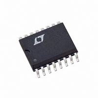
LTC1164-5CSW Linear Technology, LTC1164-5CSW Datasheet - Page 3

LTC1164-5CSW
Manufacturer Part Number
LTC1164-5CSW
Description
IC FILTR 8TH ORDR LOWPASS 16SOIC
Manufacturer
Linear Technology
Datasheet
1.LTC1164-5CNPBF.pdf
(16 pages)
Specifications of LTC1164-5CSW
Filter Type
Butterworth or Bessel Lowpass
Frequency - Cutoff Or Center
20kHz
Number Of Filters
1
Max-order
8th
Voltage - Supply
4.75 V ~ 16 V, ±2.375 V ~ 8 V
Mounting Type
Surface Mount
Package / Case
16-SOIC (0.300", 7.5mm Width)
Lead Free Status / RoHS Status
Contains lead / RoHS non-compliant
Other names
LTC1164-5CS
Available stocks
Company
Part Number
Manufacturer
Quantity
Price
Part Number:
LTC1164-5CSW
Manufacturer:
LTNEAR
Quantity:
20 000
temperature range, otherwise specifications are at T
unless otherwise specified.
PARAMETER
Maximum f
Clock Feedthrough
Wideband Noise
Input Impedance
Output DC Voltage Swing
Output DC Offset
Output DC Offset TempCo
Power Supply Current
Power Supply Range
Note 1: Absolute Maximum Ratings are those values beyond which life of
the device may be impaired.
Note 2: Connecting any pin to voltages greater than V
may cause latch-up. It is recommended that no sources operating from
external supplies be applied prior to power-up of the LTC1164-5.
ELECTRICAL CHARACTERISTICS
TYPICAL PERFOR A CE CHARACTERISTICS
–10
–20
–30
–50
–70
–80
–40
–60
CLK
0
0.1
Gain vs Frequency
V
T
A
S
= 25°C
= ±5V
FREQUENCY (kHz)
1
A
W
B
10
U
C
1164-5 G01
50
CONDITIONS
V
V
V
Input at GND, f = f
±5V, (f
±5V, (f
Input at GND, 1Hz ≥ f < f
±5V, (f
±5V, (f
V
V
V
V
V
V
V
V
+
S
S
S
S
S
S
S
S
S
S
S
or less than V
A. f
B. f
C. f
≥ ±7.5V
= ±5.0V
= Single 5V (GND = 2V)
= ±2.375V
= ±5.0V
= ±7.5V
= ±5V, (f
= ±5V, (f
= ±2.375V, T
= ±5.0V, T
= ±7.5V, T
f
(100:1, PIN 10 TO V – )
f
(140:1, PIN 10 GND)
f
(50:1, PIN 10 TO V + ,
PINS 1-13 SHORTED)
CLK
CUTOFF
CLK
CUTOFF
CLK
CUTOFF
A
CLK
CLK
CLK
CLK
= Operating Temperature Range. V
= 100kHz
= 375kHz
= 500kHz
/f
/f
/f
/f
= 1kHz
= 2.68kHz
= 10kHz
C
C
C
C
CLK
CLK
) = 100:1
) = 50:1
) = 100:1
) = 50:1
A
A
The
/f
/f
≥ 25°C
≥ 25°C
–
A
C
C
) = 100:1
) = 100:1
CLK
≥ 25°C
●
, Square Wave
denotes the specifications which apply over the full operating
CLK
Note 3: All gains are measured relative to passband gain. The filter cutoff
frequency is abbreviated as f
–15
–10
– 5
0
Passband Gain and Phase
vs Frequency
V
f
f
(50:1, PIN 10 TO V
PINS 1-13 SHORTED)
T
CLK
CUTOFF
A
0.2
S
●
●
●
●
●
●
= 25°C
= ±5V
S
= 50kHz
= ±7.5V, R
= 1kHz
0.4
CUTOFF
FREQUENCY (kHz)
±2.375
±3.70
±5.40
±1.25
MIN
70
+
,
or f
0.6
L
= 10k, f
C
LTC1164-5C
.
100 ±5%
115 ±5%
GAIN
PHASE
±4.10
±5.90
0.8
±1.50
±100
TYP
± 50
200
100
100
1.5
1.0
1.0
2.5
4.5
7.0
CLK
LTC1164-5
1164-5 G02
1.0
= 400kHz,
±160
MAX
11.0
12.5
160
4.0
4.5
7.0
8.0
±8
0
–90
–180
–270
µV
µV
µV
µV
UNITS
11645fc
µV/°C
3
MHz
MHz
MHz
RMS
RMS
RMS
RMS
mV
mA
mA
mA
mA
mA
mA
kΩ
V
V
V
V


