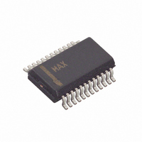
MAX7313AEG+T Maxim Integrated Products, MAX7313AEG+T Datasheet - Page 19

MAX7313AEG+T
Manufacturer Part Number
MAX7313AEG+T
Description
IC I/O EXPANDER I2C 16B 24QSOP
Manufacturer
Maxim Integrated Products
Datasheet
1.MAX7313ATG.pdf
(27 pages)
Specifications of MAX7313AEG+T
Interface
I²C
Number Of I /o
16
Interrupt Output
Yes
Frequency - Clock
400kHz
Voltage - Supply
2 V ~ 3.6 V
Operating Temperature
-40°C ~ 125°C
Mounting Type
Surface Mount
Package / Case
24-QSOP
Lead Free Status / RoHS Status
Lead free / RoHS Compliant
Figure 15. Individual (or Global) Set to 1/16
Figure 16. Individual (or Global) Set to 15/16
Figure 17. Individual (or Global) Set to 16/16
Table 11. PWM Intensity Settings (Blink Disabled)
INTENSITY
Control, Interrupt, and Hot-Insertion Protection
GLOBAL)
SETTING
OUTPUT
(OR
0xA
0xB
0xC
0xD
0x0
0x1
0x2
0x3
0x4
0x5
0x6
0x7
0x8
0x9
0xE
0xF
OUTPUT BLINK PHASE 0
LOW TIME
Static low
1
1
PWM DUTY CYCLE
10/16
11/16
12/16
13/16
14/16
15/16
REGISTER BIT = 0
1
1/16
2/16
3/16
4/16
5/16
6/16
7/16
8/16
9/16
______________________________________________________________________________________
2
2
16-Port I/O Expander with LED Intensity
2
3
3
3
4
4
4
MASTER INTENSITY TIMESLOT
MASTER INTENSITY TIMESLOT
HIGH TIME
5
5
Static low
5
15/16
14/16
13/16
12/16
11/16
10/16
6
9/16
8/16
7/16
6/16
5/16
4/16
3/16
2/16
1/16
6
6
7
7
7
8
8
8
9 10 11 12 13 14 15 16
9 10 11 12 13 14 15 16
9 10 11 12 13 14 15 16
OUTPUT BLINK PHASE 0
LED BEHAVIOR WHEN
Highest PWM intensity
Lowest PWM intensity
Full intensity, no PWM
(LED on continuously)
REGISTER BIT = 0
(LED IS ON WHEN
MASTER INTENSITY TIMESLOT CONTROL IS IGNORED
OUTPUT IS LOW)
1
1
1
2
2
2
3
3
3
OUTPUT BLINK PHASE 0
impedance
LOW TIME
Static high
4
4
4
PWM DUTY CYCLE
15/16
14/16
13/16
12/16
11/16
10/16
REGISTER BIT = 1
9/16
8/16
7/16
6/16
5/16
4/16
3/16
2/16
1/16
5
5
5
NEXT MASTER INTENSITY TIMESLOT
NEXT MASTER INTENSITY TIMESLOT
6
6
6
7
7
7
8
8
HIGH TIME
impedance
8
Static high
9 10 11 12 13 14 15 16
9 10 11 12 13 14 15 16
10/16
11/16
12/16
13/16
14/16
15/16
9 10 11 12 13 14 15 16
1/16
2/16
3/16
4/16
5/16
6/16
7/16
8/16
9/16
OUTPUT BLINK PHASE 0
LED BEHAVIOR WHEN
Highest PWM intensity
Lowest PWM intensity
LED off continuously
REGISTER BIT = 1
(LED IS ON WHEN
OUTPUT IS LOW)
19


