CC-2401K2A-CS5 Copeland Communications Inc, CC-2401K2A-CS5 Datasheet - Page 47
CC-2401K2A-CS5
Manufacturer Part Number
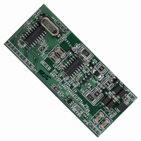
CC-2401K2A-CS5
Description
MODEM 2400BAUD SECURE 5V
Manufacturer
Copeland Communications Inc
Datasheet
1.CC-2401K2A-CS.pdf
(66 pages)
Specifications of CC-2401K2A-CS5
Data Format
V.21, V.22, V.23, Bell 103
Baud Rates
2.4k
Interface
UART
Voltage - Supply
4.2 V ~ 7 V
Mounting Type
Surface Mount
Package / Case
Module
For Use With
539-1002 - KIT EVALUATION WORLD MODEM II
Lead Free Status / RoHS Status
Contains lead / RoHS non-compliant
Other names
539-1009
CC-2401K2A-CS5
CC-2401K2A-CS5


SE1 (GPIO1), General Purpose Input/Output 1
Reset Settings = 0000_0100 (0x04)
SE2 (GPIO2), General Purpose Input/Output 2
Reset Settings = 0010_0010 (0x22)
© 2007, Copeland Communications, Inc.
*
Name
7:2
7:6
5:4
3:2
1:0
Name
Bit
Bit
Note: To be used as a GPIO pin; SE4[3] (GPE) must equal zero.
Type
Type
1
0
Bit
Bit
GPIO4[1:0]
GPIO3[1:0]
GPIO2[1:0]
GPIO1[1:0]
Reserved
GPIO5
Name
GPD5
Name
D7
GPIO4[1:0]
D7
R/W
D6
D6
Read returns Zero.
GPIO5 Data.
GPIO5.
0 = Digital input.
1 = Digital output (relay drive).
GPIO4.
00 = Digital Input.
01 = Digital output (relay drive).
10 = AOUT.
11 = INT# function defined by S08.
GPIO3.
00 = Digital Input.
01 = Digital output (relay drive).
10 = Reserved.
11 = ESC function (digital input).
GPIO2.
00 = Digital Input.
01 = Digital output (relay drive; also used for CD# function).
10 = Reserved.
11 = Digital input.
GPIO1
00 = Digital Input.
01 = Digital output ( relay drive).
10 = Reserved.
11 = Reserved.
*
.
D5
D5
GPIO3[1:0]
R/W
D4
D4
Page 47 of 66
Data Sheet
D3
D3
GPIO2[1:0]
R/W
D2
D2
Function
Function
GPD5
R/W
D1
D1
GPIO1[1:0]
R/W
GPIO5
R/W
D0
D0
CC-2401K2 Datasheet Rev 1.5
CC-2401K2
Related parts for CC-2401K2A-CS5
Image
Part Number
Description
Manufacturer
Datasheet
Request
R

Part Number:
Description:
Display Modules & Development Tools Digi Embedded ARM 2.8 LCD Display
Manufacturer:
Digi International

Part Number:
Description:
CAP 3.3UF 10V CERAMIC Y5V 0805
Manufacturer:
Yageo
Datasheet:

Part Number:
Description:
MODEM 2400 BAUD SERIAL
Manufacturer:
Copeland Communications Inc

Part Number:
Description:
MODEM 2400BAUD SECURE 3.3V
Manufacturer:
Copeland Communications Inc
Datasheet:

Part Number:
Description:
MODEM 56K V.92 SERIAL
Manufacturer:
Copeland Communications Inc

Part Number:
Description:
MODEM 56K V.92 SERIAL 5V
Manufacturer:
Copeland Communications Inc

Part Number:
Description:
MODEM 56K BAUD SERIAL
Manufacturer:
Copeland Communications Inc
Datasheet:

Part Number:
Description:
MODEM 56KBAUD SERIAL 5V
Manufacturer:
Copeland Communications Inc
Datasheet:
Part Number:
Description:
MODEM 2400BAUD SERIAL 5V
Manufacturer:
Copeland Communications Inc
Part Number:
Description:
MODEM 14.4KBAUD SERIAL 5V
Manufacturer:
Copeland Communications Inc
Part Number:
Description:
MODEM 33KBAUD SERIAL 5V
Manufacturer:
Copeland Communications Inc
Part Number:
Description:
MODEM 14.4KBAUD SERIAL 3.3V
Manufacturer:
Copeland Communications Inc
Part Number:
Description:
MODEM 33KBAUD SERIAL 3.3V
Manufacturer:
Copeland Communications Inc
Part Number:
Description:
MODEM 2400BAUD SERIAL 5V
Manufacturer:
Copeland Communications Inc
Part Number:
Description:
MODEM 14.4KBAUD SERIAL 5V
Manufacturer:
Copeland Communications Inc