2222 123 10688 Vishay, 2222 123 10688 Datasheet - Page 11
2222 123 10688
Manufacturer Part Number
2222 123 10688
Description
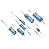
CAPACITOR ALUM ELECT 6.8UF, 35V, AXIAL
Manufacturer
Vishay
Datasheet
1.MAL212317101E3.pdf
(12 pages)
Specifications of 2222 123 10688
Capacitance
6.8µF
Capacitance Tolerance
± 20%
Voltage Rating
35V
Esr
16ohm
Life Time @ Temperature
20000 Hours @ 125°C
Height
15.3mm
Diameter
6.7mm
Capacitor Mounting
Through Hole
Rohs Compliant
No


ADDITIONAL TESTS AND REQUIREMENTS FOR EPOXY-FILLED VERSIONS SAL-AG
2281 123 8.... Form BA ± 10 %, level S, lead (Pb)-free
2222 123 8.... Form BA ± 10 %, level S, non lead (Pb)-free
Table 4
Document Number: 28355
Revision: 23-Jun-08
TEST PROCEDURES AND REQUIREMENTS
Severe vibration tests in accordance with “IEC 60068-2-6” and “MIL STD-202”, method 204, letter E, with the following details and
additions
Method of mounting:
severity 1
severity 2
severity 1 and 2
Direction and duration of motion:
severity 1
severity 2
Functioning:
severity 1
severity 2
Typical capability
Severe shock tests in accordance with “IEC 60068-2-27” and “MIL STD-202”, method 213, letter F, with the following details and
additions:
Method of mounting
Pulse shape:
severity 1
severity 2
severity 3
Direction and number of shocks:
severity 1 and 2
severity 3
Functioning
TEST
clamping both body and leads
frequency range temperature 10 to 3000 Hz; 20 to 25 °C
frequency range temperature 50 to 2000 Hz; 125 °C
vibration amplitude: 50 g or 3.5 mm, whichever is less
1 octave/minute; 3 directions (mutually perpendicular);
20 sweeps per direction (total 60 sweeps or 18 hours)
1 octave/minute; 2 directions (longitudinal and
transversal); 3 sweeps per direction
(total 6 sweeps or 1 hour)
rated voltage applied
no voltage applied
> 80 g at 10 to 3000 Hz (also at 125 °C)
clamping both body and leads
half-sine or sawtooth
1500 g; 0.5 ms (“MIL STD-202”, method 213, letter F)
3000 g; 0.2 ms
10 000 g; 0.1 ms
3 successive shocks in each direction of 3 mutually
perpendicular axes (total 18 shocks)
1 shock in any direction
rated voltage applied
For technical questions, contact: aluminumcaps2@vishay.com
Aluminum Capacitors
Solid Axial
PROCEDURE
ΔC/C: ± 10 %
tan δ ≤ 1.2 x stated limit
Z ≤ 1.4 x stated limit
DC leakage current: ≤ stated limit
no intermittent contacts
no indication of breakdown
no open circuiting
no evidence of mechanical damage
ΔC/C: ± 10 %
tan δ ≤ 1.2 x stated limit
Z ≤ 1.4 x stated limit
DC leakage current: ≤ stated limit
no intermittent contacts
no indication of breakdown
no open circuiting
no evidence of mechanical damage
Vishay BCcomponents
REQUIREMENTS
123 SAL-A
www.vishay.com
261
Related parts for 2222 123 10688
Image
Part Number
Description
Manufacturer
Datasheet
Request
R

Part Number:
Description:
CAPACITOR ALUM ELECT 10UF, 35V, AXIAL
Manufacturer:
Vishay
Datasheet:

Part Number:
Description:
CAPACITOR ALUM ELECT 2.2UF, 35V, AXIAL
Manufacturer:
Vishay
Datasheet:
Part Number:
Description:
CAPACITOR ALUM ELECT 4.7UF, 35V, AXIAL
Manufacturer:
Vishay
Datasheet:
Part Number:
Description:
CAPACITOR ALUM ELECT 22UF, 16V, AXIAL
Manufacturer:
Vishay
Datasheet:
Part Number:
Description:
CAPACITOR ALUM ELECT 10UF, 40V, AXIAL
Manufacturer:
Vishay
Datasheet:
Part Number:
Description:
CAPACITOR ALUM ELECT 4.7UF, 40V, AXIAL
Manufacturer:
Vishay
Datasheet:

Part Number:
Description:
Capacitor,1000uF,10VDC,20-% Tol,20+% Tol
Manufacturer:
Vishay
Part Number:
Description:
Capacitor,220uF,25VDC,20-% Tol,20+% Tol
Manufacturer:
Vishay
Part Number:
Description:
Capacitor,330uF,25VDC,10-% Tol,10+% Tol
Manufacturer:
Vishay
Part Number:
Description:
357-036-542-201 CARDEDGE 36POS DL .156 BLK LOPRO
Manufacturer:
Vishay
Datasheet:
Part Number:
Description:
357-036-542-201 CARDEDGE 36POS DL .156 BLK LOPRO
Manufacturer:
Vishay
Datasheet:
Part Number:
Description:
357-036-542-201 CARDEDGE 36POS DL .156 BLK LOPRO
Manufacturer:
Vishay
Datasheet:
Part Number:
Description:
357-036-542-201 CARDEDGE 36POS DL .156 BLK LOPRO
Manufacturer:
Vishay
Datasheet:
Part Number:
Description:
357-036-542-201 CARDEDGE 36POS DL .156 BLK LOPRO
Manufacturer:
Vishay
Datasheet: