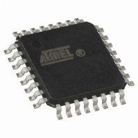
AT42QT1110-MU Atmel, AT42QT1110-MU Datasheet - Page 18

AT42QT1110-MU
Manufacturer Part Number
AT42QT1110-MU
Description
IC TOUCH SENSOR 11KEY 32QFN
Manufacturer
Atmel
Series
QTouch™r
Type
Capacitiver
Datasheet
1.AT42QT1110-AU.pdf
(48 pages)
Specifications of AT42QT1110-MU
Touch Panel Interface
10, 2-Wire
Number Of Inputs/keys
11 Key
Data Interface
Serial, SPI™
Voltage Reference
Internal
Voltage - Supply
3 V ~ 5.5 V
Current - Supply
8mA, 12mA
Operating Temperature
-40°C ~ 85°C
Mounting Type
Surface Mount
Package / Case
32-VFQFN Exposed Pad
Output Type
Logic
Interface
SPI
Input Type
Logic
Supply Voltage
3 V to 5.5 V
Dimensions
5 mm L x 5 mm W x 0.9 mm H
Output Voltage
0.7 V to 0.8 V
Temperature Range
- 40 C to + 85 C
Termination Style
SMD/SMT
Lead Free Status / RoHS Status
Lead free / RoHS Compliant
Other names
AT42QT1110-MU
AT42QT1110-MUTR
AT42QT1110-MUTR
Available stocks
Company
Part Number
Manufacturer
Quantity
Price
Part Number:
AT42QT1110-MU
Manufacturer:
AT
Quantity:
20 000
Company:
Part Number:
AT42QT1110-MU QS470
Manufacturer:
Atmel
Quantity:
19 943
4.6
4.7
4.7.1
4.7.2
4.8
4.8.1
18
Stand-alone Mode
Key Modes
Trigger Modes
AT42QT1110-MU/AT42QT1110-AU
11-key Mode
7-key Mode
Timed Trigger
The QT1110 can operate in a stand-alone mode without the use of the SPI interface. The
settings are loaded from EEPROM and the device operates in 7-key mode using the Detect
outputs.
In 11-key mode, the device can sense up to 11 keys. Alternatively, one key can be replaced by
the SYNC line as an external trigger input (see
11-key mode is configured by setting the “MODE” bit in the Device Mode setup byte (see
Section 7.4 on page
Key acquisition can be triggered in one of two ways: using the internal clock to trigger acquisition
either at a fixed repetition period or in a continuous “free run” mode (see
the SYNC pin to provide an external trigger (see
In 7-key mode, the detect outputs DETECT0 to DETECT6 become active on pins 22–27 and 30.
These outputs provide configurable PWM signals that indicate when each of the keys is
touched.
7-key mode is configured by clearing the “MODE” bit in the Device Mode setup byte (see
Section 7.4 on page
Each DETECT output can be individually configured to output a PWM signal while the matching
key is in detect or out of detect. This signal can be one of nine levels, ranging from low
(PWM = 0 percent) to high (PWM = 100 percent). This allows for the use of an indicating LED.
This is achieved by enabling the appropriate bit in the Key to LED setup byte (see
on page
Section 7.12 on page
In 11-key mode, The QT1110 can be configured to use the internal clock as a timed trigger. In
this case, the QT1110 is configured with a cycle period, such that each acquisition cycle starts a
specified length of time after the start of the previous cycle. If the cycle period is set to “0”, each
acquisition cycle starts as soon as the previous one has finished, resulting in the acquisition
cycles running back-to-back in a “free run” mode.
The use of a timed trigger, and the cycle period to be used, is set in the Device Mode setup byte
(see
• Touch mode
Section 7.4 on page
– The CHANGE pin is pulled low when one or more keys are in detect. The CHANGE
– The CHANGE pin is released when there are no keys in detect. No host
pin remains low as long as there is a key in detect, regardless of communications.
communications are required to release the CHANGE pin.
35), and setting the desired outputs levels or PWMs in setup addresses 9 to 15 (see
29).
29).
33).
29).
Section 4.8.2 on page
Section 4.8.2 on page
19).
19),
Section
4.8.1), or using
9520I–AT42–03/10
Section 7.14


