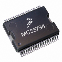
MC33794EKR2 Freescale Semiconductor, MC33794EKR2 Datasheet - Page 4

MC33794EKR2
Manufacturer Part Number
MC33794EKR2
Description
IC SENSOR ELECTRIC FIELD 54SOICW
Manufacturer
Freescale Semiconductor
Type
Sensor Interfacer
Datasheet
1.MC33794EK.pdf
(18 pages)
Specifications of MC33794EKR2
Input Type
Logic
Output Type
Logic
Interface
ISO9141
Current - Supply
7mA
Mounting Type
Surface Mount
Package / Case
54-SOIC (7.5mm Width) Exposed Pad, 54-eSOIC, 54-HSOIC
Maximum Operating Temperature
+ 85 C
Mounting Style
SMD/SMT
Lead Free Status / RoHS Status
Lead free / RoHS Compliant
Other names
MC33794EKR2
MC33794EKR2TR
MC33794EKR2TR
Available stocks
Company
Part Number
Manufacturer
Quantity
Price
Company:
Part Number:
MC33794EKR2
Manufacturer:
ROHM
Quantity:
3 200
Part Number:
MC33794EKR2
Manufacturer:
FREESCALE
Quantity:
20 000
4
Table 1. SOICW-EP TERMINAL FUNCTION DESCRIPTION (continued)
MC33794
Terminal
11–14
10
15
16
17
18
19
24
25
26
27
28
29
30
8
9
LAMP_SENSE
LAMP_MON
SHIELD_EN
PWR_MON
V
Terminal
A, B, C, D
LP_CAP
SHIELD
SIGNAL
R_OSC
DD
LEVEL
AGND
Name
V
CLK
V
V
PWR
_
DD
CC
MON
Low-Pass Filter Capacitor
5.0 V Regulator Output
Positive Power Supply
Undetected Signal
Oscillator Resistor
Analog Ground
Selector Inputs
Detected Level
Power Monitor
Formal Name
V
Lamp Monitor
Shield Driver
Shield Driver
Lamp Sense
V
DD
DD
Clock
Capacitor
Monitor
This terminal is normally connected to the LAMP_OUT terminal. The voltage at
this terminal is reduced and sent to LAMP_MON so the voltage at the lamp
terminal is brought into the range of the analog-to-digital converter (ADC) in the
MCU.
This terminal is connected through a voltage divider to the LAMP_SENSE
terminal. The voltage divider scales the voltage at this terminal so that battery
voltage present when the lamp is off is scaled to the range of the MCU ADC.
With the lamp off, this terminal will be very close to battery voltage if the lamp is
not burned out and the terminal is not shorted to ground. This is useful as a lamp
check.
This terminal is used to enable the shield signal. The shield is disabled when
SHIELD_EN is a logic low (ground)
These input terminals control which electrode or reference is active. Selection
values are shown in Table 5, Electrode Selection, page 10. These are logic level
inputs.
This is the undetected signal being applied to the detector. It has a DC level with
the low radio frequency signal superimposed on it. Care must be taken to
minimize DC loading of this signal. A shift of DC will change the center point of
the signal and adversely affect the detection of the signal.
This is the detected, amplified, and offset representation of the signal voltage on
the selected electrode. Filtering of the rectified signal is performed by a capacitor
attached to LP_CAP.
This is connected through a voltage divider to V
voltage so it will fall within the range of the ADC on the MCU.
A capacitor on this terminal forms a low pass filter with the internal series
resistance from the detector to this terminal. This terminal can be used to
determine the detected level before amplification or offset is applied. A 10 nF
capacitor connected to this terminal will smooth the rectified signal. More
capacitance will increase the response time.
A resistor from this terminal to circuit ground determines the operating frequency
of the oscillator. The MC33794 is optimized for operation around 120 kHz.
This terminal provides a square wave output at the same frequency as the
internal oscillator. The edges of the square wave coincide with the peaks
(positive and negative) of the sine wave.
This is connected through an internal voltage divider to V
reduction of the voltage so it will fall within the range of the ADC on the MCU.
A capacitor is connected to this terminal to filter the internal analog regulated
supply. This supply is derived from V
12 V power applied to this terminal will be converted to the regulated voltages
needed to operate the part. It is also converted to 5.0 V (internal V
8.5 V (internal V
This output terminal requires a 47 µF capacitor and internal V
a regulated 5.0 V for the MCU and for internal needs of the MC33794.
This terminal is connected to the ground return of the analog circuitry. This
ground should be kept free of transient electrical noise like that from logic
switching. Its path to the electrical current return point should be kept separate
from the return for GND.
This terminal connects to cable shields to cancel cable capacitance.
DD
REG) to power the MCU and external devices.
Definition
PWR
through internal V
PWR
Freescale Semiconductor
. It allows reduction of the
DD
DD
REG. It allows
CC
REG.
REG provides
CC
REG) and
Sensors


