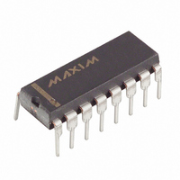
DS2175 Maxim Integrated Products, DS2175 Datasheet - Page 3

DS2175
Manufacturer Part Number
DS2175
Description
IC ELASTIC STORE T1/CEPT 16-DIP
Manufacturer
Maxim Integrated Products
Type
Memoryr
Datasheet
1.DS2175S.pdf
(12 pages)
Specifications of DS2175
Tx/rx Type
T1/CEPT
Delay Time
100ns
Capacitance - Input
5pF
Voltage - Supply
4.5 V ~ 5.5 V
Current - Supply
9mA
Mounting Type
Through Hole
Package / Case
16-DIP (0.300", 7.62mm)
Lead Free Status / RoHS Status
Contains lead / RoHS non-compliant
Available stocks
Company
Part Number
Manufacturer
Quantity
Price
Part Number:
DS21755
Manufacturer:
DALLAS
Quantity:
20 000
Company:
Part Number:
DS2175S
Manufacturer:
DALLAS
Quantity:
45
Company:
Part Number:
DS2175S
Manufacturer:
DALLAS
Quantity:
141
Part Number:
DS2175S
Manufacturer:
DALLAS
Quantity:
20 000
Company:
Part Number:
DS2175S+
Manufacturer:
Maxim Integrated Products
Quantity:
135
Part Number:
DS2175S+
Manufacturer:
DALLAS
Quantity:
20 000
Part Number:
DS2175S+TR
Manufacturer:
MAXIM/美信
Quantity:
20 000
PCM BUFFER
The DS2175 utilizes a 2–frame buffer to synchronize in-coming PCM data to the system backplane clock.
Buffer depth is mode–dependent; 2.048 MHz to 2.048 MHz applications utilize 64 bytes of buffer
memory, while all other modes are supported by 48 bytes. The buffer samples data at RSER on the falling
edge of RCLK. Output data appears at SSER and is updated on the rising edge of SYSCLK. The buffer
depth is constantly monitored by onboard contention logic; a “slip” occurs when the buffer is completely
emptied or filled. Slips automatically recenter the buffer to a one–frame depth and always occur on frame
boundaries.
DATA FORMAT
Data is presented to, and output from, the elastic store in a “framed” format. A rising edge at RMSYNC
and SFSYNC establishes frame boundaries for the receive and system sides. North American (T1) frames
contain 24 data channels of 8 bits each and an F–bit (193 bits total). European (CEPT) frames contain 32
data channels (256 bits). The frame rate of both systems is 8 KHz. RMSYNC and SFSYNC do not
require a pulse at every frame boundary; if desired, they may be pulsed once to establish frame alignment.
Internal counters will then maintain the frame alignment and may be reinforced by the next rising edge at
RMSYNC and/or SFSYNC.
PIN
10
11
12
13
14
15
16
1
2
3
4
5
6
7
8
9
SYMBOL
RCLKSEL
RCLK
RSER
RMSYNC
FSD
V
SCLKSEL
S/ P
SCHCLK
SFSYNC
SMSYNC
SSER
SYSCLK
V
SLIP
ALN
SS
DD
TYPE
O
O
O
O
O
–
–
I
I
I
I
I
I
I
I
I
PIN Description Table 1
DESCRIPTION
Receive Clock Select. Tie to V
V
Receive Clock. 1.544 or 2.048 MHz data clock.
Receive Serial Data. Sampled on falling edge of RCLK.
Receive Multifram Sync. Rising edge establishes receive side
frame and multiframe boundaries.
Frame Slip Directions. State indicates direction of last slip;
latched on slip occurrence.
Frame Slip. Active low, open collector output. Held low for 65
SYSCLK cycles when a slip occurs.
Align. Recenters buffer on next system side frame boundary when
forced low; negative edge-triggered.
Signal Ground. 0.0 volts.
System Clock Select. Tie to V
V
Serial/Parallel Select. Tie to V
applications, to V
System Channel Clock. Transitions high on channel boundaries;
useful for serial to parallel conversion of channel data.
System Frame Sync. Rising edge establishes system side frame
boundaries.
System Multiframe Sync. Slip-compensated multiframe output;
used with RMSYNC to monitor depth of store real time.
System Serial Data. Updated on rising edge of SYSCLK.
System Clock. 1.544 or 2.048 MHz data clock.
Positive Supply. 5.0 volts.
DD
DD
for 2.048 MHz.
for 2.048 MHz.
3 of 12
DD
for serial.
SS
SS
SS
for 1.544 MHz applications, to
for 1.544 MHz applications, to
for parallel backplane
DS2175


