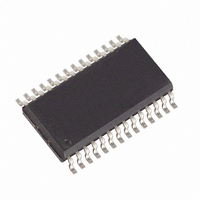
DS2109S/T&R Maxim Integrated Products, DS2109S/T&R Datasheet

DS2109S/T&R
Specifications of DS2109S/T&R
Available stocks
Related parts for DS2109S/T&R
DS2109S/T&R Summary of contents
Page 1
FEATURES Fully compliant with SCSI–1, Fast SCSI and Ultra SCSI Compatible with Plug and Play SCSI Profile Functionally compatible with DS21S07A Provides active termination for 18 signal lines 2% tolerance on termination resistors and voltage regulator Bus termination sensing Low ...
Page 2
DS2109 REFERENCE DOCUMENTS SCSI–2 (X3.131–1994) SCSI–3 Parallel Interface (X3T10/855D) Available from: Global Engineering Documents 15 Inverness Way East Englewood, CO 80112–5704 Phone: (800) 854–7179,(303) 792–2181 Fax: (303) 792–2192 PnP SCSI Specification PnP ISA Specification PnP BIOS Specification PnP Option ROM ...
Page 3
The DS2109 consists of 3 major functional blocks, Figure 2: Voltage reference, terminating resistors, and isolation switches Bus current sensing circuitry Bus ground sensing circuity When the Bus Ground Sensing Circuitry or Bus Current Sensing Circuitry determine that the SCSI ...
Page 4
DS2109 DETAILED PIN DESCRIPTION Table 1 PIN SYMBOL FCN DESCRIPTION 1 PDI I Power Down Internal. For Bus Ground Sensing Circuit connect to pin 22 of internal SCSI connector, see Figure 4. 2–6, R1...R13 T Signal Termination. 110 ohm termination. ...
Page 5
BUS GROUND SENSING CIRCUIT Figure 3 PDI PDE BUS GROUND DETECT CONFIGURATION Figure 4 INTERNAL SCSI CONNECTOR 22 26 2.2 F DS2109 PDI TPWR DISABLE TERMPWR 38 GND 36 PDE V REF 4.7 F DS2109 022698 5/10 ...
Page 6
DS2109 BUS CURRENT SENSING The DS2109 has the capability to use current sensing to determine if the SCSI bus is over– or under–terminated. A series 1 ohm resistor between pads R14 and TCS is inserted into the SCSI bus (preferably ...
Page 7
BUS CURRENT SENSE CONFIGURATION Figure 6 INTERNAL SCSI CONNECTOR 26 TERMPWR DS2109 R1 TPWR 2.2 F R13 R15 V REF R18 TCS 4.7 F R14 GND BUS CURRENT SENSE TIMING DIAGRAM Figure 7 TCS COMPARATORS LATCH –RST ...
Page 8
DS2109 DISCONNECT MODES Table 2 PDI PDE NOTE: “1” denotes pin left open circuited. WIDE SCSI CONFIGURATION Figure 8 2.2 F TERMPWR1 1 16 ...
Page 9
ABSOLUTE MAXIMUM RATINGS* Voltage on Any Pin Relative to Ground Operating Temperature Storage Temperature Soldering Temperature * This is a stress rating only and functional operation of the device at these or any other conditions above those indicated in the ...
Page 10
DS2109 NOTES: 1. PDI, PDE, TCS 2. 4.00V < TERMPWR < 5.25V. 3. 0.0V < signal lines < 3.0V. 4. All signal lines = 0.0V. 5. All signal lines open. 6. Power down enabled. 7. Guaranteed by design; not production ...


