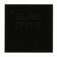
CP2101-GM Silicon Laboratories Inc, CP2101-GM Datasheet - Page 3

CP2101-GM
Manufacturer Part Number
CP2101-GM
Description
IC CTRLR BRIDGE USB-UART 28MLP
Manufacturer
Silicon Laboratories Inc
Specifications of CP2101-GM
Package / Case
28-VQFN Exposed Pad, 28-HVQFN, 28-SQFN, 28-DHVQFN
Applications
USB
Interface
USB
Voltage - Supply
3 V ~ 3.6 V
Mounting Type
Surface Mount
Maximum Operating Temperature
+ 85 C
Minimum Operating Temperature
- 40 C
Mounting Style
SMD/SMT
Operating Supply Voltage
3.6 V
Supply Current (max)
25 mA
Operating Temperature (min)
-40C
Operating Temperature Classification
Industrial
Operating Temperature (max)
85C
Package Type
QFN
Rad Hardened
No
Lead Free Status / RoHS Status
Lead free / RoHS Compliant
Lead Free Status / RoHS Status
Lead free / RoHS Compliant, Lead free / RoHS Compliant
Other names
336-1162
Available stocks
Company
Part Number
Manufacturer
Quantity
Price
Company:
Part Number:
CP2101-GM
Manufacturer:
SiliconL
Quantity:
4 094
Part Number:
CP2101-GMR
Manufacturer:
SILICON LABS/芯科
Quantity:
20 000
Table of Contents
1. System Overview..................................................................................................... 5
2. Absolute Maximum Ratings ................................................................................... 5
3. Global DC Electrical Characteristics ..................................................................... 6
4. Pinout and Package Definitions............................................................................. 7
5. USB Function Controller and Transceiver .......................................................... 12
6. Asynchronous Serial Data Bus (UART) Interface............................................... 12
7. Internal EEPROM ................................................................................................... 13
8. CP2101 Device Drivers.......................................................................................... 14
9. Voltage Regulator.................................................................................................. 15
10. Relevant Application Notes .................................................................................. 17
Document Change List ............................................................................................... 18
Contact Information .................................................................................................... 20
8.1. Virtual COM Port Drivers .................................................................................. 14
8.2. USBXpress Drivers ........................................................................................... 14
8.3. Driver Customization ........................................................................................ 14
8.4. Driver Certification ............................................................................................ 14
Table 2.1. Absolute Maximum Ratings ................................................................ 5
Table 3.1. Global DC Electrical Characteristics ................................................... 6
Table 3.2. UART and Suspend I/O DC Electrical Characteristics ........................ 6
Table 3.3. Reset Electrical Characteristics .......................................................... 6
Table 4.1. Pin Definitions for the CP2101 ............................................................ 7
Figure 4.1. QFN-28 Pinout Diagram (Top View) .................................................. 8
Figure 4.2. QFN-28 Package Drawing ................................................................. 9
Table 4.2. QFN-28 Package Dimensions............................................................. 9
Figure 4.3. Typical QFN-28 Landing Diagram ................................................... 10
Figure 4.4. Typical QFN-28 Solder Paste Recommendation ............................. 11
Figure 5.1. Typical Connection Diagram ............................................................ 12
Table 6.1. Data Formats and Baud Rates.......................................................... 13
Table 7.1. Default USB Configuration Data ....................................................... 13
Table 9.1. Voltage Regulator Electrical Specifications ....................................... 15
Figure 9.1. Configuration 1: USB Bus-Powered ................................................. 15
Figure 9.2. Configuration 2: USB Self-Powered ................................................. 16
Figure 9.3. Configuration 3: USB Self-Powered, Regulator Bypassed .............. 16
Rev. 1.8
CP2101
3


