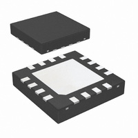
LMH0384SQE/NOPB National Semiconductor, LMH0384SQE/NOPB Datasheet - Page 9

LMH0384SQE/NOPB
Manufacturer Part Number
LMH0384SQE/NOPB
Description
IC ADAPT CBL EQUALIZER 16-LLP
Manufacturer
National Semiconductor
Datasheet
1.LMH0384SQENOPB.pdf
(16 pages)
Specifications of LMH0384SQE/NOPB
Applications
Digital Interface
Interface
SPI
Voltage - Supply
3.135 V ~ 3.465 V
Package / Case
16-LLP
Mounting Type
Surface Mount
Leaded Process Compatible
Yes
Rohs Compliant
Yes
Input Voltage
3.3 V
Supply Voltage (max)
3.45 V
Supply Voltage (min)
3.15 V
Maximum Operating Temperature
+ 85 C
Minimum Operating Temperature
- 40 C
Mounting Style
SMD/SMT
Peak Reflow Compatible (260 C)
Yes
Lead Free Status / RoHS Status
Lead free / RoHS Compliant
Other names
LMH0384SQETR
Available stocks
Company
Part Number
Manufacturer
Quantity
Price
Company:
Part Number:
LMH0384SQE/NOPB
Manufacturer:
STM
Quantity:
4 302
SPI Register Access
Setting SPI_EN high enables the optional SPI register access
mode. In SPI mode, the LMH0384 provides register access
to all of its features along with a cable length indicator, pro-
grammable output common mode voltage and swing, and
launch amplitude optimization. There are five supported 8-bit
registers in the device (see Table 1). With SPI_EN set low,
the device operates in pin mode and is footprint compatible
with the LMH0344, LMH0044, and LMH0074.
SPI WRITE
The SPI write is shown in Figure 2. The MOSI payload con-
sists of a “0” (write command), seven address bits, and eight
data bits. The SS signal is driven low, and the 16 bits are sent
to the LMH0384's MOSI input. Data is latched on the rising
edge of SCK. The MISO output is normally tri-stated during
this operation. After the SPI write, SS must return high.
SPI READ
The SPI read is shown in Figure 3. The MOSI payload con-
sists of a “1” (read command) and seven address bits. The
SS signal is driven low, and the eight bits are sent to the
LMH0384's MOSI input. The addressed location is accessed
immediately after the rising edge of the 8
data bits are shifted out on MISO starting with the falling edge
of the 8
rising edge of the 8
high.
OUTPUT DRIVER ADJUSTMENTS
The output driver swing (amplitude) and offset voltage (com-
mon mode voltage) are adjustable via SPI register 01h.
The output swing is adjustable via bits [7:5] of SPI register
01h. The default value for these register bits is “011” for a
peak to peak differential output voltage of 700 mV
output swing can be adjusted in 100 mV increments from 400
mV
The offset voltage is adjustable via bits [4:2] of SPI register
01h. The default value for these register bits is “001” for an
output offset of 1.25V. The output common mode voltage may
be adjusted in 200 mV increments, from 1.05V to 1.85V. It can
also be set to “101” for the maximum offset voltage. At this
maximum offset voltage setting, the outputs are referenced to
the positive supply and the offset voltage is around 2.1V.
LAUNCH AMPLITUDE OPTIMIZATION
The LMH0384 can compensate for attenuation of the input
signal prior to the equalizer. This compensation is useful for
applications with a passive splitter at the equalizer input or a
non-ideal input termination network, and is controlled by SPI
register 02h.
Bit 7 of SPI register 02h is used for coarse control of the
launch amplitude setting. At the default setting of “0”, the
LMH0384 operates normally and expects a launch amplitude
P-P
to 800 mV
th
clock. MOSI must be tri-stated immediately after the
P-P
th
.
clock. After the SPI read, SS must return
th
clock and the eight
P-P
. The
9
of 800 mV
for input signals with 6 dB of attenuation (400 mV
Once the coarse control is set, the LMH0384 input compen-
sation may be further fine tuned by bits [6:3] of SPI register
02h. These bits may be used to tweak the input gain stage
-22% to +40% around the coarse control setting.
CABLE LENGTH INDICATOR (CLI)
The Cable Length Indicator (CLI) provides an indication of the
length of cable attached to the input. CLI is accessible via bits
[7:3] of SPI register 03h. The 5-bit CLI ranges in decimal value
from 0 to 25 (“00000” to “11001” binary) and increases as the
cable length is increased. Figure 6 shows typical CLI values
vs. Belden 1694A cable length. CLI is valid for Belden 1694A
cable lengths of 0-140m at 2.97 Gbps, 0-200m at
1.485 Gbps, and 0-400m at 270 Mbps.
APPLICATION OF CLI: EXTENDING 3G REACH
An application of CLI is to extend the 3G reach in systems
which have margin in the jitter budget. This allows for addi-
tional cable reach at 2.97 Gbps at the expense of slightly
higher output jitter. The extended 3G reach mode provides
15m of additional Belden 1694A cable reach, with an increase
of output jitter at this longer cable length of 0.05 to 0.1 UI.
The extended 3G reach mode is accessible via bit 2 of SPI
register 00h. In order to achieve longer 3G cable reach while
still maintaining the performance at HD and SD data rates, a
state machine can be implemented as shown in Figure 7.
(Note: If this procedure is not followed, the maximum equal-
izable cable lengths for HD and SD data rates will be limited
to less than what can be achieved in normal mode).
FIGURE 6. CLI vs. Belden 1694A Cable Length
P-P
. Bit 7 may be set to “1” to optimize the LMH0384
www.national.com
30083011
P-P
).


