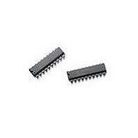
HCTL-2022 Avago Technologies US Inc., HCTL-2022 Datasheet - Page 14

HCTL-2022
Manufacturer Part Number
HCTL-2022
Description
QUADRATURE DECODER/COUNTER INTER
Manufacturer
Avago Technologies US Inc.
Type
Quadrature Decoder/ Counter Interface ICr
Datasheet
1.HCTL-2022.pdf
(21 pages)
Specifications of HCTL-2022
Package / Case
20-DIP (0.300", 7.62mm)
Mounting Type
Through Hole
Voltage - Supply
4.5 V ~ 5.5 V
Applications
Encoder to Microprocessor
Interface
8-Bit Tristate
Maximum Operating Temperature
+ 100 C
Minimum Operating Temperature
- 40 C
Lead Free Status / RoHS Status
Contains lead / RoHS non-compliant
Lead Free Status / RoHS Status
Lead free / RoHS Compliant, Contains lead / RoHS non-compliant
Other names
Q2414340A
Available stocks
Company
Part Number
Manufacturer
Quantity
Price
Company:
Part Number:
HCTL-2022
Manufacturer:
AVAGO
Quantity:
1 340
Quadrature Decoder
The quadrature decoder decodes the incoming filtered
signals into count information. This circuitry multiplies
the resolution of the input signals by a factor of one, two
or four (1X, 2X, 4X decoding) depending on the resolu-
tion mode. When using an encoder for motion sensing,
the user benefits from the selectable resolution by being
able to provide better system control.
The quadrature decoder samples the outputs of the CHA
and CHB filters. Based on the past binary state of the two
signals and the present state, it outputs a count signal
and a direction signal to the integral position counter.
4
Figure 12. Signal Propagation through Digital Noise Filter
filtered
filtered
filtered
CHA
CHB
CHA
CHB
CLK
chB
CHI
CHI
state
clk
chA
Noise Spike
Tes
t
1
E
Te
2
Telp
3 t
t
E
CLK
3
t
E
t
ES
4
t
ES
t
E
t
ES
Figure 13 shows the quadrature states of Channel A and
Channel B signals. The?4x decoder mode will output
a count signal for every state transition (count up and
count down). Figure 14 shows the valid state transi-
tions for 2x and 1x decoder modes. The 2x/1x decoder
will output a count signal at respective state transition,
depending on the counting direction. Channel A lead-
ing channel B results in counting up. Channel B leading
channel A results in counting down. Illegal state transi-
tions, caused by faulty encoders or noise severe enough
to pass through the filter, will produce an erroneous
count.
t
ES
4
Transitions
Valid State
1
3
count
down
count up
2


