2-1926732-5 TE Connectivity, 2-1926732-5 Datasheet - Page 2
2-1926732-5
Manufacturer Part Number
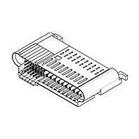
2-1926732-5
Description
High Speed / Modular Connectors 25S 10P R/A PLUG PIN AND TAB CONTACT
Manufacturer
TE Connectivity
Specifications of 2-1926732-5
Pcb Mount Alignment
Without
Pcb Mount Retention
With
Pcb Mounting Orientation
Right Angle
Make First / Break Last
Yes
Product Line
MINIPAK HDL
Ul File Number
E28476
Termination Method To Pc Board
Through Hole - Press Fit
Sealed
No
Number Of Power Positions
10
Operating Voltage Reference
AC
Operating Voltage (vac)
250
Hot Pluggable
No
Tail Length (mm [in])
3.3 [0.13]
Tail Orientation
In-line
Profile Height (y-axis) (mm [in])
8.00 [0.315]
Number Of Signal Positions
25
Number Of Positions
35
Pcb Mount Retention Type
Screw Mount
Selectively Loaded
Yes
Centerline (mm [in])
2.00 [0.079]
Centerline, Power Contacts (mm [in])
2.75 [0.108]
Underplate Material Thickness (µm [?in])
1.27 [50.000]
Length (x-axis) (mm [in])
51.71 [2.040]
Width (z-axis) (mm [in])
32.50 [1.2795]
Number Of Rows
1
Mating Retention
Without
Tail Plating Material
Bright Tin-Lead
Contact Type
Pin
Contact Base Material
Copper
Contact Plating, Mating Area, Material
Gold or Palladium Nickel or Performance Based
Contact Plating, Mating Area, Thickness (µm [?in])
0.762 [30]
Tail Plating, Thickness (µm [?in])
0.5 [20]
Underplate Material
Nickel
Contact Design
Single Beam
Connector Style
Plug
Mating Alignment
With
Housing Material
Crystal Polymer
Ul Flammability Rating
UL 94V-0
Housing Color
Black
Mating Alignment Type
Passive Guide
Connector Contact Configuration (no. Of Pos./type)
25/Signal, 10/AC Power
Custom Configurable
No
Rohs/elv Compliance
RoHS compliant, ELV compliant
Lead Free Solder Processes
Wave solder capable to 240°C, Wave solder capable to 260°C, Wave solder capable to 265°C
Rohs/elv Compliance History
Always was RoHS compliant
Agency/standard
UL, CSA
Ul Rating
Recognized
Ul Voltage Rating (vac)
250
Csa Certified
Yes
Operating Temperature (°c [°f])
-40 – +125 [-40 – +257]
Pcb Thickness, Recommended (mm [in])
1.40 [0.055]
Applies To
Printed Circuit Board
Board-to-board Configuration
Co-Planar
Contact Transmits (typical Application)
Signal (Data)/ Power
Application Use
Board-to-Board
Pick And Place Cover
Without
Packaging Method
Tray
Lead Free Status / Rohs Status
Details


|
|
3.2.
3.3.
3.4.
Rev B
Materials
Materials used in the construction of this product shall be as specified on the applicable product
drawing.
Ratings
!
!
!
Signal Contact
Perform ance and Test Description
Product is designed to m eet the electrical, m echanical and environm ental perform ance requirem ents
specified in Figure 1. Unless otherwise specified, all tests shall be perform ed at am bient environm ental
conditions.
NOTE
Contact
Signal
Power
Power
Single
Type
Voltage: See Figure 1
Current: See Figure 2
Tem perature: -40 to 125 C
3
Signal Contacts
(amperes)
For low level current or non-energized testing, connectors are applied to test boards with 2, 2
ounce thick copper power planes. Circuit carried on 2 commoned 2 ounce layers. For higher
current testing, connectors are applied to test boards with 4, 2 ounce thick copper power
planes. Circuit carried on 4 commoned 2 ounce layers. Further current testing results are
available in 502-1259. A test system consists of 24 power contacts on 2.75 mm contact pitch
and 40 signal contacts on 2.0 mm contact pitch.
Contact Pitch
NOTE
Signal Contacts
(mm)
2.75
5.50
25 Adjacent
2
Current Per Contact (am peres) At 30 C Tem perature Rise
1
Denotes Safety Extra Low Voltage (SELV) circuits.
Primary Circuits
60 (see Note)
Within
200
NR
Steady State - 2.75 mm spacing
Number of contacts energized
Volts RMS or DC
Secondary Circuits
Figure 1
Figure 2
60 (see Note)
Primary to
NR
NR
Current per Power Contact
(amperes)
Ground Circuits
60 (see Note)
Primary to
200
NR
26
1
22
2
Secondary Circuits
20
4
60 (see Note)
60 (see Note)
Within
200
17
8
12
16
108-2325
24
13
2 of 9
Related parts for 2-1926732-5
Image
Part Number
Description
Manufacturer
Datasheet
Request
R

Part Number:
Description:
03P UMNL PLUG HSG
Manufacturer:
TE Connectivity
Datasheet:

Part Number:
Description:
CONN BARRIER BLOCK 19POS 9.53MM
Manufacturer:
Tyco Electronics
Datasheet:
Part Number:
Description:
CONN BARRIER BLOCK 19POS 9.53MM
Manufacturer:
Tyco Electronics
Datasheet:
Part Number:
Description:
CONN BARRIER BLOCK 19POS 8.26MM
Manufacturer:
Tyco Electronics
Datasheet:
Part Number:
Description:
BARRIER STRIP 19POS VERT .438"
Manufacturer:
Tyco Electronics
Datasheet:
Part Number:
Description:
TRI-BARRIER STRIP 19POS VERT SGL
Manufacturer:
Tyco Electronics
Datasheet:

Part Number:
Description:
TERM BLCK RCPT 19POS VERT 5.08MM
Manufacturer:
Tyco Electronics
Datasheet:
Part Number:
Description:
TERM BLK SIDE ENTRY 19POS 5.08MM
Manufacturer:
Tyco Electronics
Datasheet:

Part Number:
Description:
PGA SOCKET, 370POS, THROUGH HOLE
Manufacturer:
Tyco Electronics
Datasheet:

Part Number:
Description:
Power to the Board 09P PLUG HSG NAT
Manufacturer:
TE Connectivity
Datasheet:

Part Number:
Description:
Manufacturer:
TE Connectivity
Datasheet:

Part Number:
Description:
Manufacturer:
TE Connectivity
Datasheet:

Part Number:
Description:
Manufacturer:
TE Connectivity
Datasheet:

Part Number:
Description:
Manufacturer:
TE Connectivity
Datasheet:

Part Number:
Description:
Manufacturer:
TE Connectivity
Datasheet: