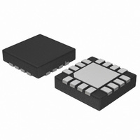
NCN4557MTR2G ON Semiconductor, NCN4557MTR2G Datasheet - Page 11

NCN4557MTR2G
Manufacturer Part Number
NCN4557MTR2G
Description
IC SMART CARD/SIM DUAL 16-QFN
Manufacturer
ON Semiconductor
Datasheet
1.NCN4557MTR2G.pdf
(12 pages)
Specifications of NCN4557MTR2G
Applications
*
Interface
*
Voltage - Supply
*
Package / Case
16-TFQFN Exposed Pad
Mounting Type
Surface Mount
Lead Free Status / RoHS Status
Lead free / RoHS Compliant
Available stocks
Company
Part Number
Manufacturer
Quantity
Price
Company:
Part Number:
NCN4557MTR2G
Manufacturer:
ON Semiconductor
Quantity:
405
•
•
Input Schmitt Triggers
Figure 3) have built−in Schmitt trigger circuits to prevent
the NCN4557 against uncontrolled operation. The typical
dynamic characteristics of the related pins are depicted in
Figure 14.
†For information on tape and reel specifications, including part orientation and tape sizes, please refer to our Tape and Reel Packaging
OFF
V
Specifications Brochure, BRD8011/D.
OUTPUT
ORDERING INFORMATION
ON
NCN4557MTG
NCN4557MTR2G
All the logic input pins (excepted I/O and CRD_I/O,
this state or 8 ms after the ENABLE pin is set LOW in
the other cases.
CRD_I/O is forced to LOW about 8 ms after the
ENABLE pin is set LOW.
Then CRD_V
DD
Figure 14. Typical Schmitt Trigger Characteristics
CRD_RSTA/B
CRD_CLKA/B
CRD_V
Figure 13. NCN4557 Power Down Sequence
CRD_IOA/B
ENABLE
CC
A/B
Device
CC
0.2 x V
Supply Shuts Off
0.4 V
or
DD
0.7 x V
T
OFF
~ 8.0 ms
DD
INPUT
http://onsemi.com
(Pb−Free)
(Pb−Free)
NCN4557
Package
QFN−16
QFN−16
11
Shutdown Operating
the application it is possible to put the NCN4557 in a
shutdown mode by setting LOW the pin ENABLE. On the
other hand the device enters automatically in a shutdown
mode when V
ESD Protection
Model ESD voltage protection in excess of 8 kV for all the
CRD pins (CRD_IOA & B, CRD_CLKA & B,
CRD_RSTA & B, CRD_V
other pins (microcontroller side) sustain at least 2 kV.
These values are guaranteed for the device in its full
integrity without considering the external capacitors added
to the circuit for a proper operating. Consequently in the
operating conditions it is able to sustain much more than
8 kV on its CRD pins making it perfectly protected against
electrostatic discharge well over the Human Body Model
ESD voltages required by the ISO7816 standard (4 kV).
Printed Circuit Board Layout
and efficient operating of the device in its mobile or
portable environment and fully exploit its performance.
possible to the device pins (CRD_V
V
behaviors (ripple and noise). It is recommended to use
ceramic capacitors.
connected to the ground. A relatively large ground plane is
recommended.
BAT
In order to save power or for other purpose required by
The NCN4557 CRD interface features an Human Body
Careful layout routing will be applied to achieve a good
The bypass capacitors have to be connected as close as
The exposed pad of the QFN−16 package will be
) in order to reduce as much as possible parasitic
DD
becomes lower than 1.0 V typically.
CC
3000 / Tape & Reel
A & B and GND). All the
123 Units / Rail
Shipping
CC
A and B, V
†
DD
or


