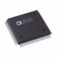
AD9887KS-100 Analog Devices Inc, AD9887KS-100 Datasheet - Page 34

AD9887KS-100
Manufacturer Part Number
AD9887KS-100
Description
IC INTRFACE ANALOG/DVI 160-MQFP
Manufacturer
Analog Devices Inc
Datasheet
1.AD9887AKSZ-100.pdf
(40 pages)
Specifications of AD9887KS-100
Rohs Status
RoHS non-compliant
Applications
Graphic Cards, VGA Interfaces
Interface
Analog and Digital
Voltage - Supply
3.15 V ~ 3.45 V
Package / Case
160-MQFP, 160-PQFP
Mounting Type
Surface Mount
AD9887
12
12
12
12
Bit 5
(VSYNC
Detect)
0
1
X
AVS = 1 means Sync separator.
AVS = 0 means VSYNC input.
The override bit is in Register 12H, Bit 3.
7 AIO—Active Interface Override
This bit is used to override the automatic interface selec-
tion (Bit 3 in Register 11H). To override, set this bit to
Logic 1. When overriding, the active interface is set via
Bit 6 in this register.
AIO
0
1
The default for this register is 0.
6 AIS—Active Interface Select
This bit is used under two conditions. It is used to select
the active interface when the override bit is set (Bit 7).
Alternately, it is used to determine the active interface
when not overriding but both interfaces are detected.
Table XXXVIII. Active Interface Select Settings
AIS
0
1
The default for this register is 0.
5 Active Hsync Override
This bit is used to override the automatic Hsync selection
(Bit 2 in Register 11H). To override, set this bit to Logic
1. When overriding, the active Hsync is set via Bit 4 in
this register.
Override
0
1
The default for this register is 0.
4 Active Hsync Select
This bit is used under two conditions. It is used to select
the active Hsync when the override bit is set (Bit 5). Alter-
nately, it is used to determine the active Hsync when not
overriding but both Hsyncs are detected.
Table XXXVII. Active Interface Override Settings
Table XXXVI. Active VSYNC Results
Table XXXIX. Active Hsync Override Settings
Result
Autodetermines the Active Interface
Override, Bit 6 Determines the Active Interface
Result
Autodetermines the Active Interface
Override, Bit 4 Determines the Active Interface
Result
Analog Interface
Digital Interface
Override
0
0
1
AVS
0
1
Bit 2 in 12H
12
12
12
12
Table XL. Active HSYNC Select Settings
Select
0
1
The default for this register is 0.
3 Active VSYNC Override
This bit is used to override the automatic VSYNC selection
(Bit 1 in Register 11H). To override, set this bit to Logic 1.
When overriding, the active interface is set via Bit 2 in
this register.
Override
0
1
The default for this register is 0.
2 Active VSYNC Select
This bit is used to select the active VSYNC when the
override bit is set (Bit 3).
Table XLII. Active VSYNC Select Settings
Select
0
1
The default for this register is 0.
1 COAST Select
This bit is used to select the active COAST source. The
choices are the COAST input pin or VSYNC. If VSYNC
is selected, the additional decision of using the VSYNC
input pin or the output from the sync separator needs to
be made (Bits 3, 2).
Select
0
1
The default for this register is 0.
0 PWRDN
This bit is used to put the chip in full power-down. This
powers down both interfaces. See the section on Power
Management for details of which blocks are actually
powered down. Note, the chip will be unable to detect
incoming activity while fully powered-down.
Select
0
1
The default for this register is 1.
Table XLIII. COAST Select Settings
Table XLIV. Power-Down Settings
Table XLI. Active VSYNC Override Settings
Result
Autodetermines the Active VSYNC
Override, Bit 2 Determines the Active VSYNC
Result
COAST Input Pin
VSYNC (See Above Text)
Result
HSYNC Input
Sync-on-Green Input
Result
VSYNC Input
Sync Separator Output
Result
Power-Down
Normal Operation


