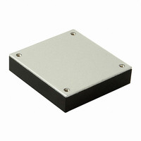
VHB75W-Q48-S24 CUI Inc, VHB75W-Q48-S24 Datasheet

VHB75W-Q48-S24
Specifications of VHB75W-Q48-S24
VHB75W-Q48-S24
Related parts for VHB75W-Q48-S24
VHB75W-Q48-S24 Summary of contents
Page 1
... MODEL VHB75W-Q24-S3R3 VHB75W-Q24-S5 VHB75W-Q24-S12 VHB75W-Q24-S15 VHB75W-Q24-S24 VHB75W-Q24-S48 VHB75W-Q48-S3R3 VHB75W-Q48-S5 VHB75W-Q48-S12 VHB75W-Q48-S15 VHB75W-Q48-S24 VHB75W-Q48-S48 notes: 1. see output derating (page 4) 2. input currents are measured at nominal input voltage 3. efficiency is measured at nominal line, full load INPUT parameter conditions/description input voltage range under voltage lockout ...
Page 2
... PART NUMBER: VHB75W OUTPUT parameter conditions/description voltage accuracy transient response 25% step load change external trim adj. range ripple & noise (20MHz BW) 3.3V, 5V 12V& 15V 24V 48V temperature coefficient short circuit protection continuous line regulation 5 6 load regulation over voltage protection trip range nom. ...
Page 3
... PART NUMBER: VHB75W MECHANICAL DRAWING th 20050 SW 112 Ave. Tualatin, Oregon 97062 DESCRIPTION: half-brick dc-dc converter phone phone 503.612.2300 fax fax 503.612.2383 page date 04/2011 www.v-infinity.com ...
Page 4
... APPLICATION NOTES 1. OUTPUT DE-RATING The operating case temperature range for VHB75W is -40 ~ +100°C. When operating the VHB75W series, proper derating or cooling is needed. The maximum case temperature under any operating condition should not exceed 100°C. Power Dissipated vs Ambient Temperature and Air Flo w Ambient Temperature ,Ta(Deg ...
Page 5
... The fuse rating will depend on the input range and should allow for the maximum current at the lowest input volt- age, as shown in this equation: Ipeak = 150%*Pout/(η η *Vmin). In the previous example of VHB75W-Q24-S5, the peak input current at 9V was calculated to be 15. fuse may be suitable for this application. Make sure the fuse voltage rating is higher than the maximum input voltage. ...
Page 6
... R trim-down o, nom is the Where: R o,nom , nominal output voltage Table 1. For example, to trim-up the output voltage of 5.0V is calculated module (VHB75W-Q48-S5 4.6V, R trim-up = 6.3 (KΩ) Ω Ω 7.2 8.2 Table 2 13.304 14.76 16.67 13.0476 phone 503.612.2300 fax phone 10KΩ ...
Page 7
... PART NUMBER: VHB75W 8. OUTPUT OCP AND SHORT-CIRCUIT PROTECTION Output overload and short circuit conditional will cause the output voltage to decline or shutdown altogether. is not over 100°C, the output recovers automatically when the short or OCP conditions are removed. In the case of slight overloading, the output voltage may not shut down, but the converter may build up heat over time, causing over-temperature shutdown ...
Page 8
... PART NUMBER: VHB75W 12. OUTPUT SERIES CONNECTIONS Two or more converters can be connected in series to obtain a higher output voltage. To prevent output reverse biasing each other in case of a short, add a Schottky diode on each output in reverse polarity, as shown in the diagram. In the event of a short, the con- verters will forward-bias the diodes and the output reversal will be limited to one diode drop (about 0 ...
Page 9
... PART NUMBER: VHB75W 15. INPUT FILTERING AND EMI INTERFERENCE The VHB75W converters have input capacitors that control input current ripple and the associated EMI interference. However, it has not been tested to a formal standard for conducted emissions. Additional filtering may be needed to ensure compliance to an EMI standard ...
Page 10
... PART NUMBER: VHB75W 16. OUTPUT FILTERING The converter has built-in capacitors at the output to control ripple and noise. If desired, additional output capacitance can be introduced at the input to the powered equipment. Recommended starting point: one 10μF tantalum and one 1μF ceramic capacitor in parallel at the output. ...


